Connecting a video switcher, Connecting a sync signal generator – Vaddio BRC-H900 Operating User Manual
Page 70
In
s
ta
llat
ion
a
nd
Conne
c
tio
ns
Connections
GB
70
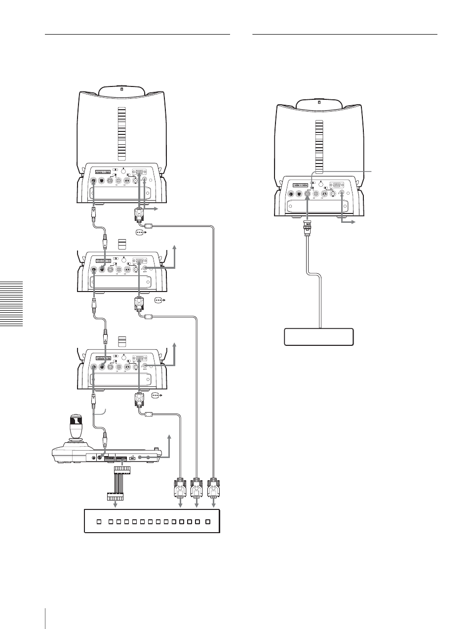
Connecting a Video Switcher
Use a commercially available video switcher to switch
between the multiple camera signals to be output.
For connection with a video switcher, refer to the
Operating Instructions of the switcher.
Connecting a Sync Signal
Generator
To connect a single camera
RGB/COMPONENT
VISCA RS-422
1 2 3 4 5 6 7 8 9
EXT SYNC IN
IR SELECT
75
1 2 3
OFF
ON
HD
SD
IN VISCA RS-232 OUT
SDI OUT
DC IN 12V
R
VIDEO
S VIDEO
RGB/COMPONENT
VISCA RS-422
1 2 3 4 5 6 7 8 9
EXT SYNC IN
IR SELECT
75
1 2 3
OFF
ON
HD
SD
IN VISCA RS-232 OUT
SDI OUT
DC IN 12V
R
VIDEO
S VIDEO
RGB/COMPONENT
VISCA RS-422
1 2 3 4 5 6 7 8 9
EXT SYNC IN
IR SELECT
75
1 2 3
OFF
ON
HD
SD
IN VISCA RS-232 OUT
SDI OUT
DC IN 12V
R
VIDEO
S VIDEO
MODE
VISCA
1
9
1
9
RS-422
ON/OFF
TALLY/CONTACT
RS-232C
CONTACT(TALLY)
!
TALLY
CONTACT
DC IN 12V
Third to Seventh
BRC-900
to the AC adaptor
(supplied)
VISCA
RS-232C IN
RS-232C cable
VISCA RS-232C
OUT
Second
BRC-H900
First
BRC-H900
RM-BR300 Remote
Control Unit
VISCA RS-232C
to
CONTACT
TALLY/
CONTACT
RGB/
COMPONENT
Video switcher (commercially available)
VISCA
RS-232C IN
RS-232C
cable
VISCA RS-232C
OUT
to
RGB/
COMPONENT
RS-232C cable
VISCA
RS-232C IN
to
c
o
mpone
nt
video input
Conn
ect
ing
cab
le wit
h D-
sub
15-pin c
onnect
o
rs (com
merc
ial
ly a
v
ailab
le)
Connec
ti
ng cab
le
wit
h D-s
ub
15-
pi
n connec
to
rs
(c
omm
e
rcially a
v
ail
a
b
le)
to
RGB/
COMPONENT
to the AC
adaptor
(supplied)
to the AC adaptor
(supplied)
to the AC adaptor (supplied
with the RM-BR300)
RGB/COMPONENT
VISCA RS-422
1 2 3 4 5 6 7 8 9
EXT SYNC IN
IR SELECT
75
1 2 3
OFF
ON
HD
SD
IN VISCA RS-232 OUT
SDI OUT
DC IN 12V
R
VIDEO
S VIDEO
75-ohm termination
switch: ON
EXT SYNC IN
75-ohm coaxial cable
to SYNC OUT
Sync signal generator
to the AC adaptor
(supplied)