Connecting the bru-sf10 hd optical multiplex unit, Connecting a vtr equipped with hd-sdi input, Connectors – Vaddio BRC-H900 Operating User Manual
Page 68: Connecting the bru-sf10 hd optical multiplex, Unit
In
s
ta
llat
ion
a
nd
Conne
c
tio
ns
Connections
GB
68
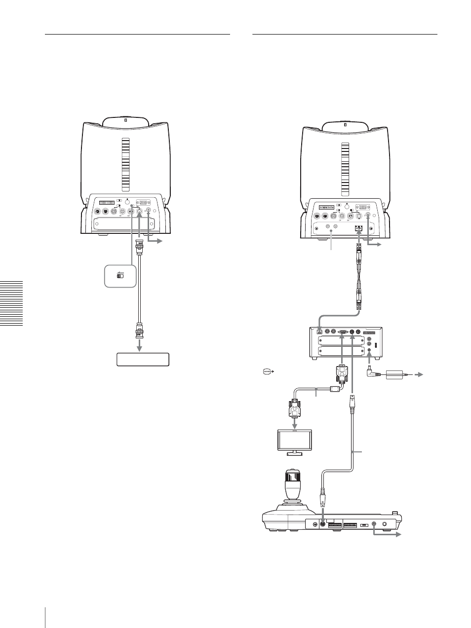
Connecting a VTR Equipped with
HD-SDI Input Connectors
Set the HD/SD select switch on the camera to HD, and
turn on the camera. You can output the signal from the
camera by converting it into a signal compliant with
HD-SDI standards (SMPTE 292 serial digital interface).
Connecting the BRU-SF10 HD
Optical Multiplex Unit
When you install an optional BRBK-SF1 Optical
Multiplex Card in the camera, you can connect the
camera to the BRU-SF10 Optical Multiplex Unit using
the CCFC-S200 Optical Fiber Cable. This allows you to
control the camera from up to 2,000 m (6,562 feet) away.
RGB/COMPONENT
VISCA RS-422
1 2 3 4 5 6 7 8 9
EXT SYNC IN
IR SELECT
75
1 2 3
OFF
ON
HD
SD
IN VISCA RS-232 OUT
SDI OUT
DC IN 12V
R
VIDEO
S VIDEO
SD
HD
to the AC adaptor
(supplied)
SDI OUTPUT
Connecting cable
with BNC connectors
to HD-SDI input
HDCAM, etc., equipped with an
HD-SDI input connectors
RGB/COMPONENT
VISCA RS-422
1 2 3 4 5 6 7 8 9
EXT SYNC IN
IR SELECT
75
1 2 3
OFF
ON
HD
SD
IN VISCA RS-232 OUT
SDI OUT
DC IN 12V
R
VIDEO
S VIDEO
CAMERA
IN
IN
VISCA
EXT SYNC
OUT
RS232C
OUT
RGB/COMPONENT
VISCA RS422
FUNCTION
L
1
10
AUDIO OUT
DC IN 12V
R
1 2 3 4 5 6 7 8 9
to the AC adaptor
(supplied)
BRBK-SF1 HD Optical
Multiplex Card
CCFC-S200 Optical
Fiber Cable
VISCA RS-232C IN
CAMERA
BRU-SF10
HD Optical
Multiplex Unit
RGB/COMPONENT
connecting cable
with D-sub 15-pin
connectors
(commercially
available)
HD monitor, etc.
RS-232C cable
(supplied with the
RM-BR300 and
BRU-SF10)*
VISCA RS-232C
RM-BR300 Remote Control Unit
* The VISCA RS-422 connection is also available if you use the
VISCA RS-422 connectors.
Optical connector
to RGB/
component
input
to AC outlet
HD camera
BRC-H900
to the AC adaptor
(supplied with the
RM-BR300)