Nor-Lake Refrigeration Systems User Manual
Page 7
09/14 Rev. E 101628
7
Line Sizing Example:
Find the Suction Line size under the following conditions.
Refrigerant:
R-404A
Suction Temp:
-20°F (-28.89°C)
Evaporator Capacity at 10° TD:
36,000 BTU/Hr
Length of Line:
100 ft.
Valves:
1 (Globe)
Elbows:
4
Solution
Step 1: Scaled or estimated at 100 feet
Step 2: From Table 3 under temperature of
–20°F, find column under 100’
Step 3: Find 36,000 BTU/Hr along the side of Table 3. Follow this row to where it
intersects with column found in step 2. Line size of 1-
3/8” O.D.
Step 4: One globe shut-off valve and four elbows
Step 5: From Table 1 under the 1-
3/8” O.D. column –
1 Globe Valve = 36
4 Elbows (4x4) = 16
Total = 52
Step 6:
Sum of the line length and equivalents is 100’ + 52’ = 152’
Step 7: Using the new total length, the line size should be 1-
5/8” O.D. instead of 1-
3/8” O.D. in order to hold the pressure drop equivalent of 2°F.
Liquid Lines: The major concerns for liquid line installations are to avoid excessive pressure
drop and to ensure a solid column of liquid to the expansion valve. Note: The expansion valve
sensing bulb must be strapped to the suction line immediately exiting the evaporator on the right
or left side. Refer to Table 2 or 3 to determine the proper liquid line size. The liquid line solenoid
valve should be installed in the liquid line just ahead of the expansion valve. The solenoid
valve should be disassembled prior to brazing to avoid possible heat damage. Use only
refrigeration grade copper tubing Type K or Type L for suction and liquid lines, or in accordance
with local codes.
All refrigerant piping should enter the condensing unit and evaporator coil through the knockouts as
provided. Use only
silver bearing hard solder such as silfos, unibraze, or similar type “hard solder”.
Do not use soft solder for any brazed refrigeration line joints. A small amount of dry nitrogen
should be bled into the piping during all brazing operations. This will help minimize scale formation
and oxidation inside the copper tubing. Keep all tubing free of metal chips, foreign matter, and
moisture during installation. The compressors for R-404A systems contain POE oil. DO NOT
leave service valves open to the atmosphere for over five minutes. This will contaminate the
oil and cause damage to the system.
When making brazed connections, care must be taken so as not to damage any closures, wiring, or
electrical connections. Secure all refrigerant line tubing with straps or hangers as required per code.
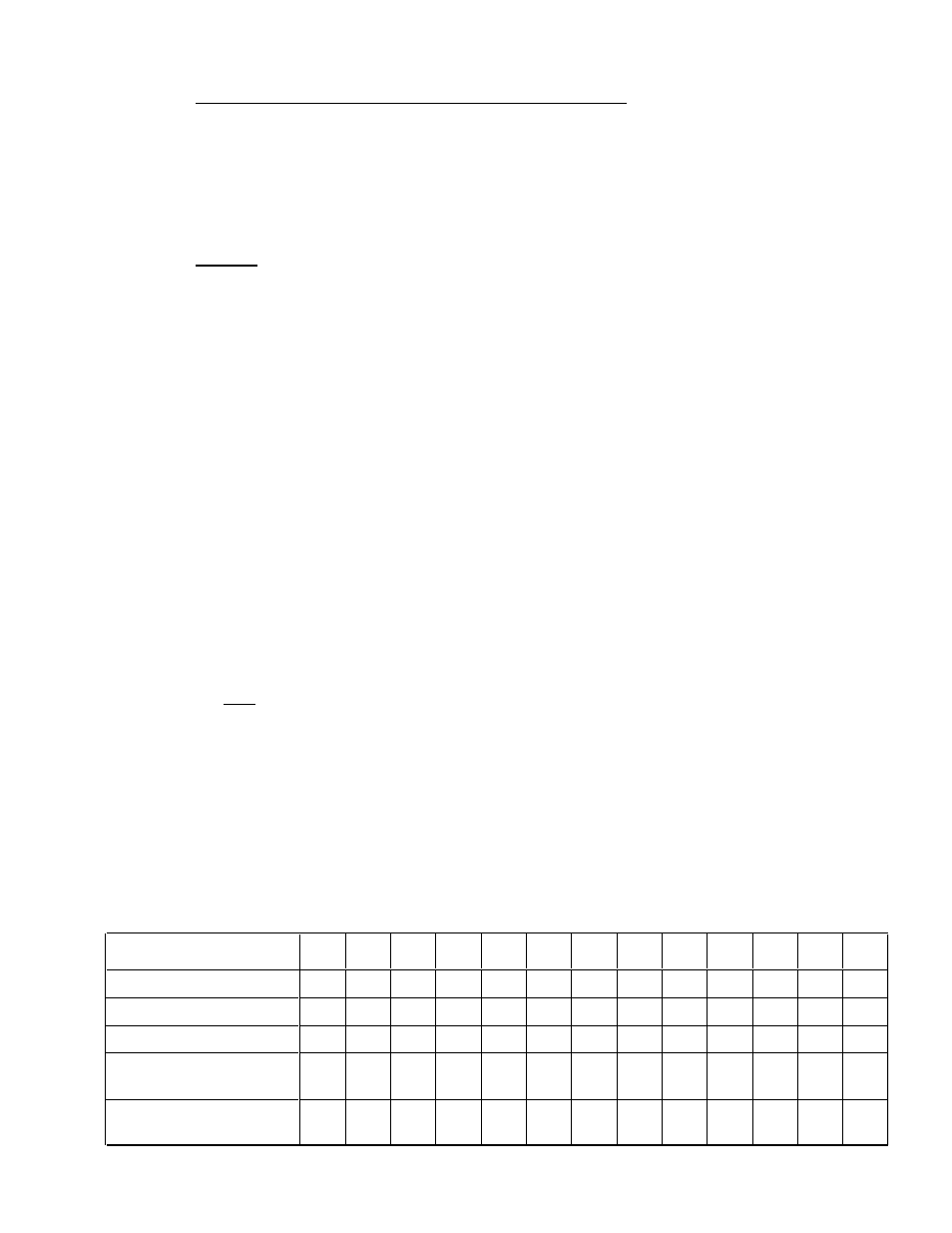
TABLE 1
– Equivalent feet for Valves and Fittings
Copper Tube O.D. Type "L" 1/2
5/8
7/8
1-1/8 1-3/8 1-5/8 2-1/8 2-5/8 3-1/8 3-5/8 4-1/8 5-1/8 6-1/8
Globe Valv e (Open)
14
16
22
28
36
42
57
69
83
99
118
138
168
Angle Valv e (Open)
7
9
12
15
18
21
28
34
42
49
57
70
83
90¡ Turn Through Tee
3
4
5
6
8
9
12
14
17
20
22
28
34
Tee (Straight Through)
Sweep Below
.75
1
1.5
2
2.5
3
3.5
4
5
6
7
9
11
90¡ Elbow or Reducing Tee
(Straight Through)
1
2
2
3
4
4
5
7
8
10
12
14
16