Nor-Lake Refrigeration Systems User Manual
Page 12
09/14 Rev. E 101628
12
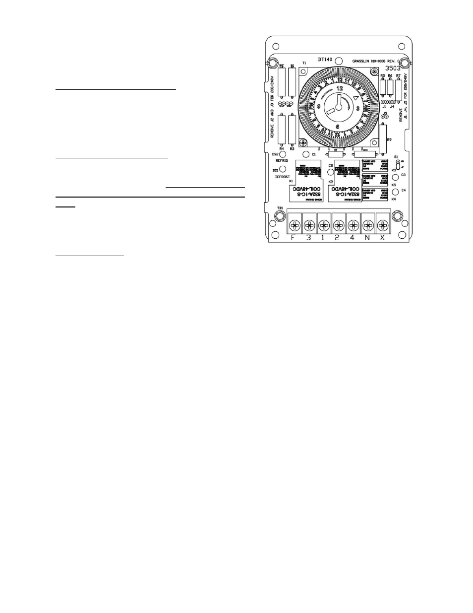
DEFROST TIME SWITCH
1. Setting the correct time of day: Simply rotate the
minute hand clockwise until the correct time of
day on the outer dial is aligned with the triangle
marker on the inner dial. In referring to the
illustration, the correct time of day shown is 8:00
a.m.
2. Number of defrosts per day: The time switch is
factory set to provide four defrosts per day. If
more defrosts are required, move additional white
tabs at the desired time. No more than two
consecutive tabs should be set at any one
time. Each white tab constitutes 15 minutes of
defrost time. If the four defrost periods provided
are more than necessary, push white tabs back
toward the center of the dial.
3. Fail-Safe feature: The fail-safe of the timer is
factory set at 30 minutes. The function of this device is to terminate the defrost cycle and revert
back to the cooling cycle if a system malfunction occurs during defrost. No adjustment of this
device should ever be necessary. Lengthening the fail-safe time will not lengthen the
defrost cycle.
Note: The defrost times are factory set at 10:00 a.m., 4:00 p.m., 10:00 p.m., and 4:00 a.m. This
setting will provide adequate defrosting for a normal installation.
WARNING: The fail-safe feature is a safety mechanism and should never be used to control the
length of defrost. This feature is provided to protect the contents of the freezer from damage should
the system fail to revert to the cooling cycle because of mechanical difficulties.
PRE-CHARGED REFRIGERANT LINES (If applicable)
By employing self-sealing refrigeration couplings, the condensing unit, the unit cooler, and the
connecting tubing are separately pre-charged with refrigerant and leak tested at the factory before
shipment. Follow these simple steps to install the connecting tubing:
1. Carefully uncoil the suction line. This line is covered with a continuous length of sponge rubber
insulating tubing.
2. Carefully uncoil the liquid line. This is the smaller diameter, bare copper tube.
3. Before making any connections, determine the routing of both lines and carefully hand bend
them to suit the situation. Keep the bend radius rather large to prevent kinking of the tubing. It is
a general practice to route the suction and liquid line parallel and close together in the
installation.
4. The pre-charged lines will have a 90° bend on one end. If the pre-charged lines are to exit
through the walk-in wall, the 90° end of the lines will be connected to the condensing unit. If the
pre-charged lines are to exit through the ceiling of the walk-in, the 90° end of the lines will be
connected to the unit cooler.