Installation – Nor-Lake Refrigeration Systems User Manual
Page 4
09/14 Rev. E 101628
4
INSTALLATION
GENERAL
Installation of all equipment, piping, and electrical must be done in accordance with local and
national codes. Installation and service of this equipment must be performed by qualified and
experienced refrigeration mechanics. Correct installation is necessary to obtain optimum
performance and customer satisfaction.
UNIT COOLER MOUNTING
IMPORTANT: If the Walk-in box is located outdoors, the unit cooler must be installed before the
installation of the membrane roof.
Unit coolers are equipped with four or six mounting brackets, depending on size, capable of
supporting the weight of the unit cooler during shipping and mounting within the cold room.
Care must be taken not to place the unit cooler on the drain pan to avoid damage to the
pan, drain fitting, or pan defrost heaters on low temperature unit coolers.
The unit cooler has a draw through evaporator design, drawing air across the coil and
discharging it into the room from the fans. Therefore, for proper airflow, it is necessary to allow a
minimum distance between the cold room wall and the air inlet side of the unit cooler of 12
inches for low profile, and 24 inches for standard profile, unit coolers.
The unit cooler must be located to provide good air circulation to all areas of the cold room.
Units should not be located above or close to doors where outside air would be drawn into the
evaporator and cold room when the door is opened.
Unit coolers must be located a sufficient distance from walls, beams, other units, or obstructions
to permit unrestricted air flow on both the entering and discharge air faces.
Space at each end of the unit cooler is a concern for installation convenience and possible
future service. Twelve inches is normally a sufficient distance at the ends of the unit cooler for
tubing and wiring connections.
Unit coolers are designed to mount directly to the cold room insulated ceiling panel using the
nylon-threaded rods, nuts, and washers provided. Care must be taken to mount the unit cooler
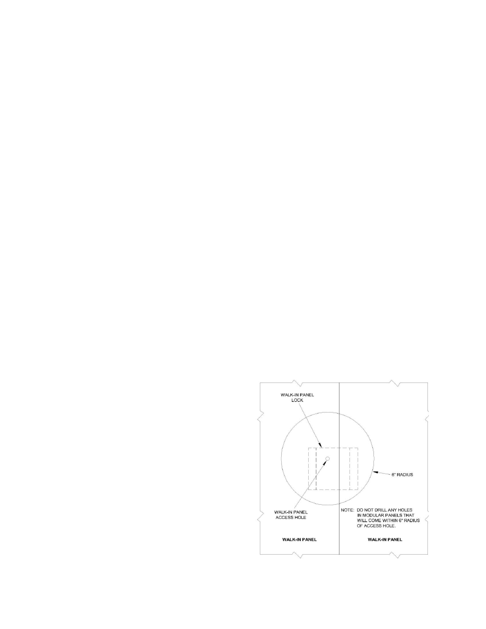
level so condensate drains properly. CAUTION: Do not drill any holes within a six-inch radius
from the center of any panel lock access hole.
See Figure 1.
1. Locate and mark the unit cooler mounting
holes on the ceiling panel.
2. Move the unit cooler and drill the holes
using a
3/8” drill bit.
3. Insert the nylon-threaded rod through the
ceiling panel from the outside.
4. Using a hammer, carefully drive the pallet
nut on the rod flush to the ceiling panel.
5. Mount the unit cooler and tighten the
mounting nuts, being careful not to over
tighten.
6. The seam between the top of the unit and
the cold room ceiling panel must be
sealed. A NSF LISTED sealant for this
purpose is provided with the cold room
hardware box.
Figure 1