A113, Assembly & installation instructions – Hubbardton Forge 139610 User Manual
Page 3
H U B B A R D T O N F O R G E . C O M
hand-forged, vermont-made lighting and accessories
154 RT. 30 SOUTH
•
CASTLETON, VERMONT 05735
All designs and images ©1989-2014 Hubbardton Forge
®
. All rights reserved.
19838 Rev C
Assembly & Installation Instructions
If you need further assistance, or find that you are missing any parts, please contact the dealer from which you purchased this product.
We hope you enjoy your fixture!
* Hubbardton Forge will not be liable for injury or damage caused by improper installation, lamping or use of this fixture.
To Install Fixture
(Continued)
2. Using suitable wire connectors (not provided) connect
fixture wires to supply (white to white and black to
black). Connect all ground wires to green ground
screw (Q).
CAUTION: MAKE SURE WIRE CONNECTORS ARE TWISTED ON
SECURELY, AND NO BARE WIRE IS EXPOSED.
3. Slide fixture canopy (O) with fixture attached, over
threaded studs (P) and push firmly to ceiling making
sure that no wires are pinched between fixture canopy
(O) and ceiling. Fasten with the barrel knobs (N). Be
sure studs are fully seated in the barrel knobs.
4. Check fixture for height (see “To Assemble Fixture”
step 2). Tighten all three set screws in clutch with the
supplied hex wrench to securely fasten the fixture to
the canopy.
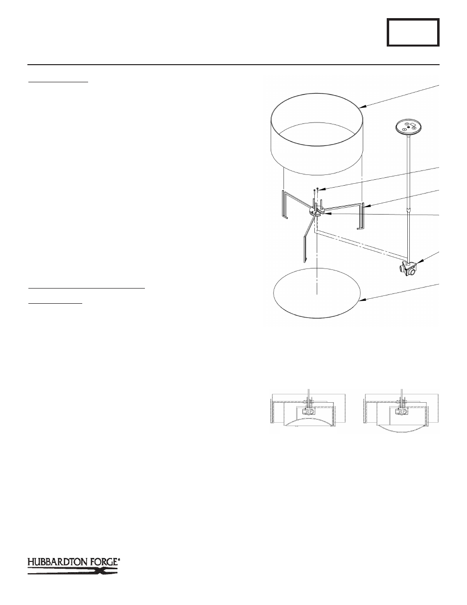
To Install Inner Shade and Glass
(Figure 5 & 9)
Component Parts
I Socket Assembly
S Shade
T Ball Screw (2)
U Support Arms (3)
V Inner Spider
W Glass Diffuser
1. Place shade (S) into notches of support arms (U).
2. Slip glass diffuser (W) curved side up at an angle into
support arms (U) and rotate to rest on the arms. It may be
necessary to flex on support arm slightly to install diffuser.
See Figure 9 for correct orientation of diffuser.
3. Move shade (S) and inner spider assembly (V) up and over
socket assembly (I) and secure with ball screws (T).
4. Lift Shade (S) to install light bulbs.
5. Restore electricity at main breaker box.
A113
For Adjustable Shade Pendant Model 139610
Page 3 of 4
(Continued)
(Figure 5)
T
S
W
U
I
V
(Figure 5)
DIFFUSER INSTALLED
CORRECTLY
DIFFUSER INSTALLED
INCORRECTLY
(Figure 9)