Hubbardton Forge 136403 User Manual
A235, Assembly & installation instructions
Assembly & Installation Instructions
A235
For Axis Pendant 13-6403 & 13-6403F
Page 1 of 4
Hand-Forged,
Vermont-Made Lighting and Accessories
P.O. Box 827, 154 Route 30 South, Castleton, Vermont 05735
24159
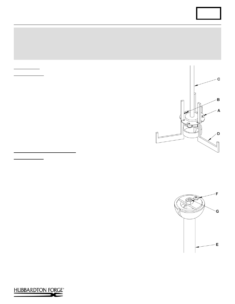
Disassemble
(Figure 1)
Component Parts
A Screws
(3)
B Locking Screw
C Upper
Assembly
D Lower
Assembly
1. Carefully unpack the fixture from the carton.
2. Remove locking screw (B) from upper assembly (C).
3. Loosen the three screws (A) remaining. It is not necessary to totally
remove them.
4. Turn lower assembly (D) counter clockwise until both assemblies
come apart. Save all parts for later use.
To Complete Fixture Assembly
(Figures 2 & 3)
Component Parts
C Upper
Assembly
E Canopy Pipe Assembly
F 8-32
Screw
G Cable Gripper Assembly
H Canopy
I Aircraft
Cable
J Top
Diffuser
K Cable
Gripper
Caution: Be sure power is off at the main breaker box prior to installation.
1. Remove 8-32 screw (F) and save for later use.
2. Lift cable gripper assembly (G) from canopy pipe assembly (E) (Figure 2).
3. Slip top diffuser (J) onto upper assembly (C) until it rests above sockets.
4. Slip wires and aircraft cable (I) through hole in the bottom of canopy (H).
5. Slip canopy (H) onto upper assembly (C) and allow it to rest on top of fixture.
6. Thread the wires and aircraft cable (I) from the upper assembly (C) into and
through the canopy pipe assembly (E).
7. Lower canopy pipe assembly (E) into upper assembly (C) until it bottoms out.
(continued)
CAUTION: FAILURE TO INSTALL THIS FIXTURE PROPERLY MAY RESULT IN SERIOUS PERSONAL
INJURY OR DEATH AND PROPERTY DAMAGE. We recommend installation by a licensed electrician.
This product must be installed in accordance with applicable installation code(s), by a person familiar with the
construction and operation of the product and the hazards involved.*
Caution: Do not exceed maximum wattage noted on fixture. Use only recommended bulbs with fixture.
(Figure 2)
(Figure 1)