1. ps200/ch200 schematic – Campbell Scientific PS200/CH200 12 V Charging Regulators User Manual
Page 24
PS200/CH200 12 V Charging Regulators
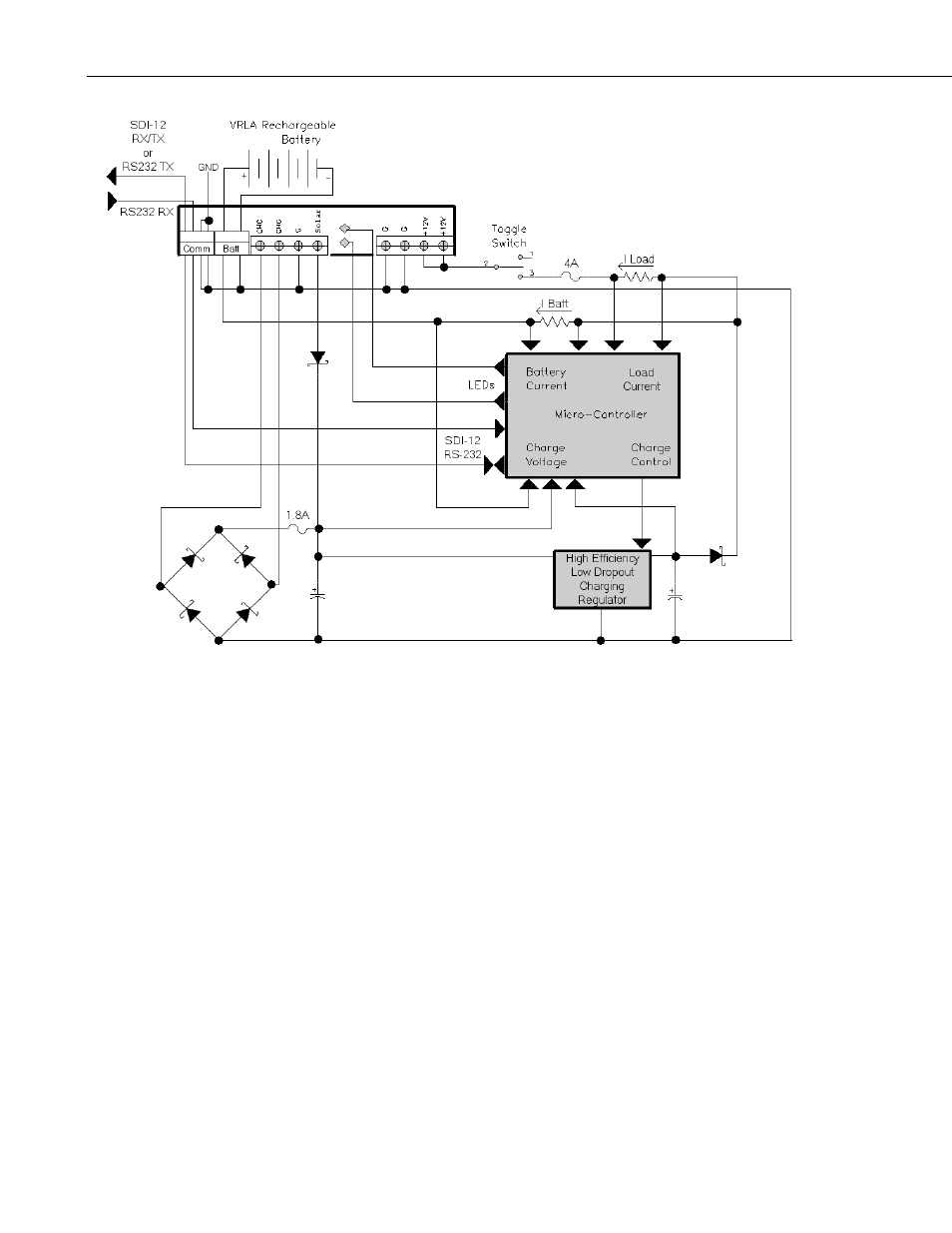
FIGURE 5-1. PS200/CH200 schematic
Charging power for the PS200/CH200 is typically supplied by an unregulated
solar panel, AC/AC transformer, or AC/DC converter. As illustrated in
FIGURE 4-1, the CHARGE – CHARGE terminals are connected to a diode
bridge, accommodating either AC or DC voltages from a charge source.
Because of the diode bridge, polarity does not matter when connecting sources
to the CHARGE – CHARGE input terminals. In order to protect AC/AC or
AC/DC sources when charging discharged batteries, the CHARGE – CHARGE
input terminals offer an approximately 1.1 amps DC (1.2 A RMS) current
limit. The SOLAR – G input terminals are intended for connection to solar
panels, or other high-current DC sources. Polarity definitely matters on the DC
only SOLAR – G input terminals, with positive connected to SOLAR and the
return or negative connected to G, with reversal protection included. The
SOLAR – G input terminals have an input current limit of approximately 3.6
amps, making the PS200/CH200 well suited for
70 watt or smaller solar panels.
The PS200/CH200 can be simultaneously powered from both the CHARGE –
CHARGE and SOLAR – G input terminals, as the internal diodes will route
power from the source with the highest input voltage. This allows for an AC
mains powered application with a solar panel for back-up. If the reverse is
needed – solar power as the primary supply and AC as the secondary supply –
then a solar panel should be used with a 24 vdc output and an AC, or AC to
DC, source with a voltage output less than the solar panel voltage.
16