3 hook up power to datalogger, Hook up power to datalogger, Hook up communication cable to datalogger if used – Campbell Scientific PS200/CH200 12 V Charging Regulators User Manual
Page 17: 8. wiring, Harness, Plugged into battery connector
PS200/CH200 12 V Charging Regulators
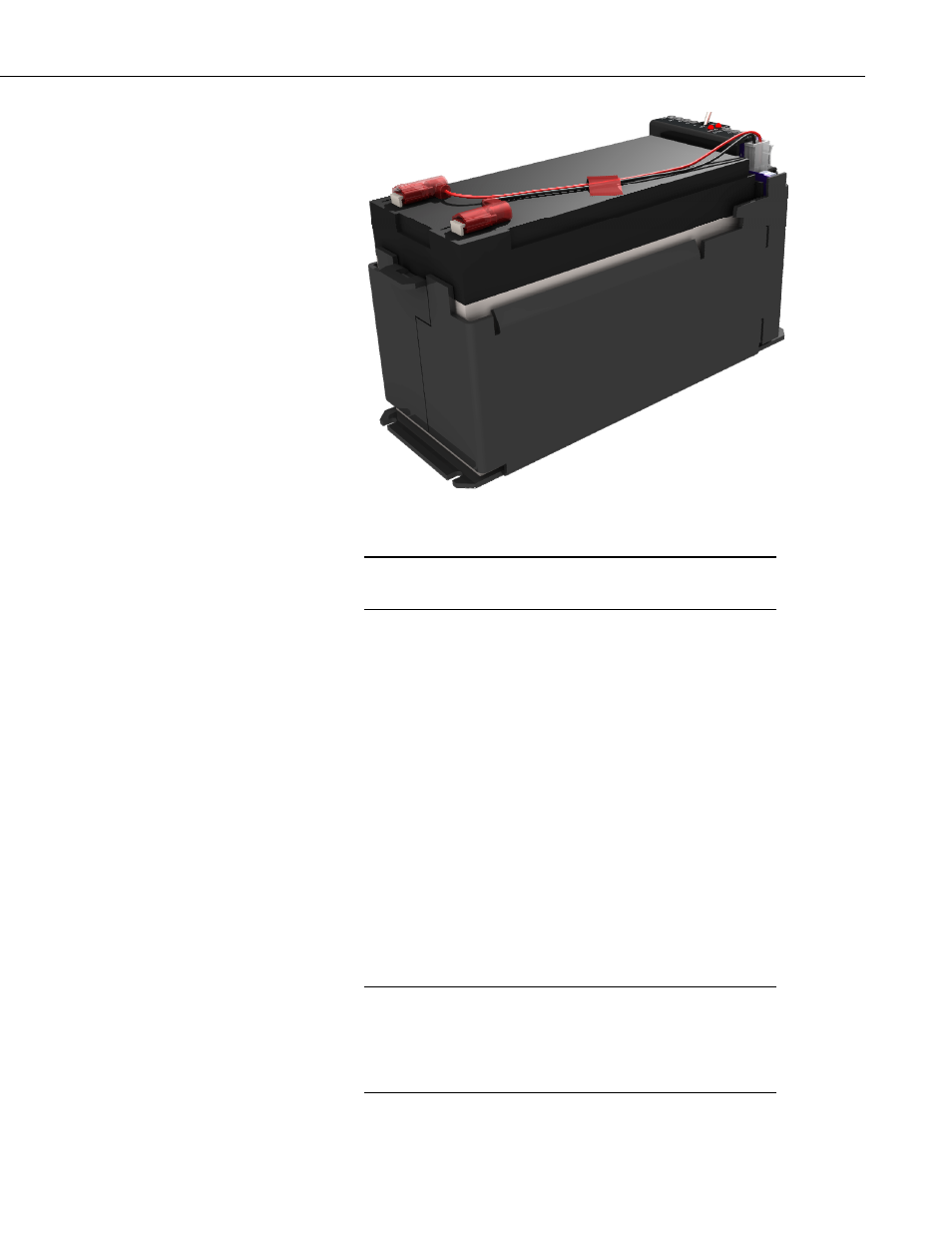
FIGURE 3-8. Wiring harness plugged into battery connector
When connecting the battery the “CHG” LED will briefly flash
red and then go out.
NOTE
3.3 Hook Up Power to Datalogger
Both the PS200 and the CH200 come with a 1 foot black wire attached to one
of the G terminal blocks and a 1 foot red wire attached to one of the 12V
terminal blocks. Attach the red wire from the power supply to the datalogger
Power terminal block marked 12V (Campbell Scientific part number 3768).
Attach the black wire from the power supply to the datalogger Power terminal
block marked “G”.
3.4 Hook Up Communication Cable to Datalogger If Used
Skip this step if a CH/PS200 communication interface cable is not being used.
Plug the power supply SDI-12 or RS-232 communication cable to the
connector marked “COMM”. This cable is polarized and will only plug in one
way. Push the connector all the way into the mating connector until it locks in
place. Wire the leads into the appropriate datalogger channels. An example of
SDI-12 wiring is shown in FIGURE 6-6. An example of RS-232 wiring is
shown in FIGURE 6-7.
This cable is NOT required for normal operation of the power
supply! It is only required if the datalogger has been
programmed to collect information from the power supply. See
Section 6.2, SDI-12, and Section 6.3, RS-232 Interface, for how
to use these cables.
NOTE
9