C.1.3 speed as a function of distance, C.1.3, C-1. cpi – Campbell Scientific CDM-VW300 Series Dynamic Vibrating-Wire Analyzer System User Manual
Page 80
Appendix C. CDM Devices and CPI Bus
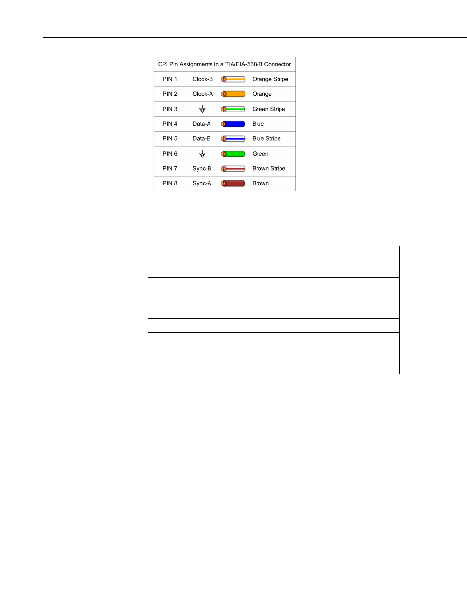
FIGURE C-1. CPI pin assignments
C.1.3 Speed as a Function of Distance
TABLE C-1. Maximum Potential Speed as a Function of Distance
1
Bit Rate (kbps)
Cable Length, m (ft)
1000 45
(150)
500 91
(300)
250 182
(600)
125 365
(1200)
50 914
(3000)
25 1219
(4000)
1
for a two-node CDM network under optimal conditions
Cable lengths shown in the preceding table can usually be adapted to CPI
networks containing multiple CDM devices if the total distance for all cable in
a network does not exceed the given length.
For most CPI bus deployments, all CDM devices should be set with a CPI Bit
Rate setting of Auto Detect
1
. Doing so allows the bit rate to be controlled by
either the CPISpeed() CRBasic instruction, or the CPI Bit Rate setting of the
SC-CPI interface
1
. The CPISpeed() setting takes priority. When a CDM device
is set to Auto Detect, it initializes into the mode given to it by the SC-CPI
interface, which comes from either the SC-CPI setting or the CPISpeed()
instruction. Any CDM device that is set to a bit rate that differs from the
current SC-CPI setting will not operate on the CPI network, and the COMM
Status indicator light on the CDM device will flash red.
1
The SC-CPI interface and all CDM devices can be configured using Campbell
Scientific Device Configuration Utility (DevConfig). CDM-VW300 series analyzers
can also be configured using DVWTool software.
C-2