1 cdm-vw300 to pc connection, 2 cdm-vw300 to sensor connection, Cdm-vw300 to pc connection – Campbell Scientific CDM-VW300 Series Dynamic Vibrating-Wire Analyzer System User Manual
Page 48: Cdm-vw300 to sensor connection, 4. usb port on the cdm-vw300, 5. three-wire vibrating-wire sensor leads
CDM-VW300 Series Dynamic Vibrating-Wire Analyzers
7.7.1 CDM-VW300 to PC Connection
A PC to CDM-VW300 USB connection is used in a laboratory-mode
installation and in the initial setup and troubleshooting of field-mode
installations.
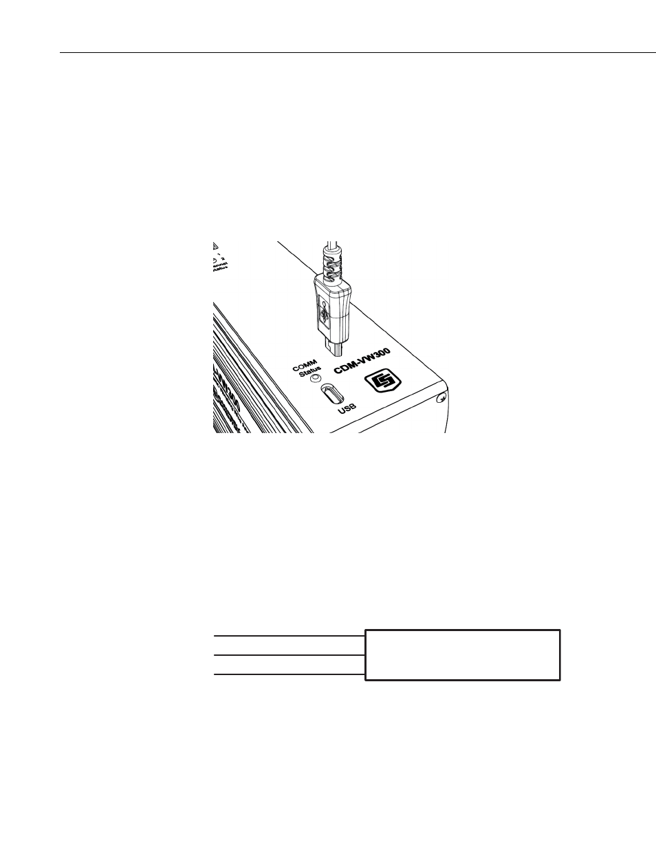
Connect a male-USB to type-micro-B male-USB cable between the PC and the
CDM-VW300 analyzer; pn 27555, provided in the CDM network kit (pn
29370), which is shipped with each analyzer, can be used. The type-micro-B
male-USB connector connects to the CDM-VW300. The USB port is located
on the analyzer as shown in FIGURE 7-4, USB port on the CDM-VW300.
FIGURE 7-4. USB port on the CDM-VW300
When the connection is made, DVWTool or DevConfig can be used to
communicate with and configure the analyzer. DVWTool is the preferred
software tool.
7.7.2 CDM-VW300 to Sensor Connection
Typical single-coil vibrating-wire sensors come with either three- or five-wire
connection leads. Refer to the specifications of a particular sensor to
understand the function of each lead.
Coil
Coil
Shield / Sensor Ground
Vibrating-Wire Sensor
FIGURE 7-5. Three-wire vibrating-wire sensor leads
As illustrated in FIGURE 7-5 and FIGURE 7-6, in the three-wire
configuration, two wires are provided as connections to the coil circuit of the
sensor. The third wire is a shield wire to be connected to ground. Most
38