Appendix b. sc-cpi datalogger to cpi interface, B.1 introduction, B.2 quickstart – Campbell Scientific CDM-VW300 Series Dynamic Vibrating-Wire Analyzer System User Manual
Page 75: B.3 overview, Appendix b, See appendix b
Appendix B. SC-CPI Datalogger to CPI
Interface
B.1 Introduction
The SC-CPI is designed to interface the CR3000, CR1000, and CR800
dataloggers to a network of CDMs (Campbell Distributed Modules) using the
CPI bus communications protocol. Only one SC-CPI interface is required per
datalogger. The datalogger and the SC-CPI should be installed in the same
enclosure.
B.2 Quickstart
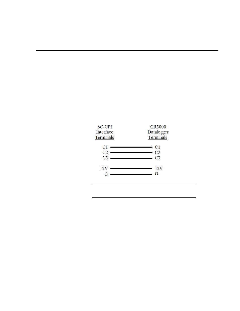
The following figure shows SC-CPI to CR3000, CR1000, or CR800 series
datalogger connection wiring. Cable length should not exceed five feet.
SC-CPI module connects to terminals C1, C2, C3 (not the
CR3000 SDM-C1, SDM-C2, SDM-C3).
NOTE
B.3 Overview
The SC-CPI allows Campbell Scientific CR3000, CR1000, and CR800
dataloggers to interface to CDM modules. The datalogger communicates with
the SC-CPI module using control ports C1, C2 and C3.
There are two LED indicator lights on the SC-CPI module. The indicator lights
show status of the link and give a visual indication that it is operating correctly.
The LED closest to the CPI port shows status of the CPI bus. The LED closest
to the terminal block shows status of the serial connection to the datalogger.
Connection to the datalogger consists of connecting 12V and G terminals of
one device to the other. Power can come from the datalogger, but may also be
provided by another source. A ground connection to the datalogger is required
for a reference for the data signals. A ground-wire connection from the ground
B-1