2 laboratory-mode installation procedure, Laboratory-mode installation procedure, 2. 12 vdc power connection on the cdm-vw300 – Campbell Scientific CDM-VW300 Series Dynamic Vibrating-Wire Analyzer System User Manual
Page 22
CDM-VW300 Series Dynamic Vibrating-Wire Analyzers
6.1.2 Laboratory-Mode Installation Procedure
.1.2 Laboratory-Mode Installation Procedure
The following procedure sets up the measurement system in laboratory mode:
The following procedure sets up the measurement system in laboratory mode:
1. Install DVWTool software on the PC. Do this before connecting the CDM-
VW300 to the PC. DVWTool installation automatically installs drivers for
the CDM-VW300 USB connection.
Reference Section 7.1.1, Software and Driver Installation.
1. Install DVWTool software on the PC. Do this before connecting the CDM-
VW300 to the PC. DVWTool installation automatically installs drivers for
the CDM-VW300 USB connection.
Reference Section 7.1.1, Software and Driver Installation.
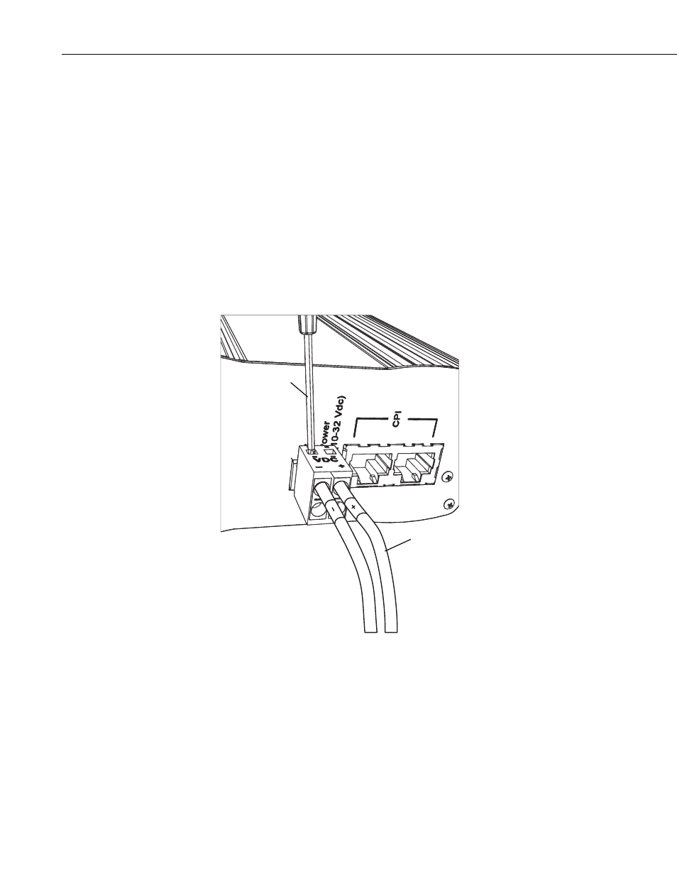
2. Connect 12 Vdc power to the CDM-VW300 as shown in FIGURE 6-2.
Reference Section 7.4, Using Power Supplies.
Campbell Scientific pn 29796, a 24 Vdc, 1670 mA wall charger, is
recommended.
2. Connect 12 Vdc power to the CDM-VW300 as shown in FIGURE 6-2.
Reference Section 7.4, Using Power Supplies.
Campbell Scientific pn 29796, a 24 Vdc, 1670 mA wall charger, is
recommended.
FIGURE 6-2. 12 Vdc power connection on the CDM-VW300
Leads from
pn 13947
transformer
Insert small
screwdriver
to open gates.
3. Connect a type-A male to type-micro-B male USB cable (Campbell
Scientific pn 27555, supplied with the analyzer) between the CDM-
VW300 and the PC as shown in FIGURE 6-3.
Reference Section 7.7.1, CDM-VW300 to PC Connection.
12