2 field-mode installation, 1 field-mode installation equipment, 2 field-mode installation procedure – Campbell Scientific CDM-VW300 Series Dynamic Vibrating-Wire Analyzer System User Manual
Page 28: Field-mode installation, Field-mode installation equipment, Field-mode installation procedure, 7. field data-acquisition system
CDM-VW300 Series Dynamic Vibrating-Wire Analyzers
are shaded red), consult Section 7.12.2.1, Monitoring with
DVWTool Software, for troubleshooting help.
6.2 Field-Mode Installation
IMPORTANT — Do not connect the CDM-VW300 analyzer or SC-CPI
interface to a PC until AFTER installing DVWTool 1.0 or later or DevConfig
2.04 or later. Consult Section 7.1.1, Software and Driver Installation, for more
information.
A simple field-mode configuration, using one CDM-VW300, is covered in this
section. Additional details concerning field-mode configuration and daisy-
chaining power and RJ45 connections are discussed in Section 7, System
Operation. Capacity of the power supply is a critical element of field
installations. Most field-mode installations will require continuous ac power or
large solar panels and batteries.
6.2.1 Field-Mode Installation Equipment
The following components are used in a field-mode installation:
• Vibrating-wire sensors
• CDM-VW300 measurement modules
• SC-CPI interface
• Datalogger
• Datalogger power supply
• Personal computer (PC)
• DVWTool analyzer software
• Datalogger support software (LoggerNet, PC400, or RTDAQ)
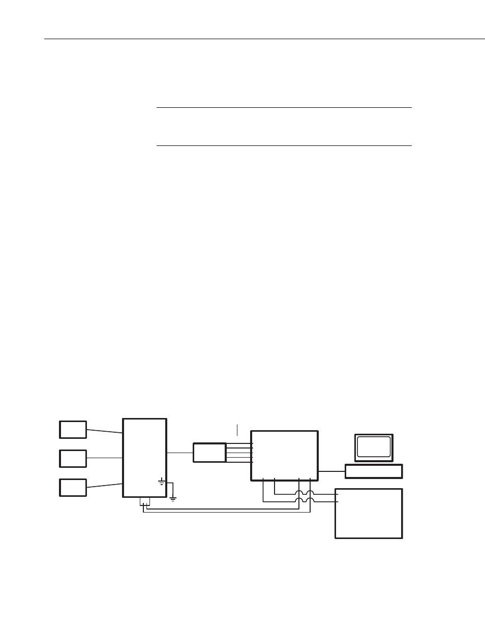
6.2.2 Field-Mode Installation Procedure
FIGURE 6-7 illustrates the final form of a simplified field-mode installation.
With reference to this figure, work through the following procedure. Reference
Section 7.7, System Connections, for more information.
PC
LoggerNet
Vibrating-Wire
Sensors
CDM-
VW300
RJ-45 to
RJ-45
pn 29526
Cable
SC-CPI
12 Vdc and G
Connection
CR3000
Datalogger
G 12V
C1
C2
C3
12V
G
C1
C2
C3
12V
G
12V
G
G 12V
Power In
12 Vdc
Ground
Power Supply
FIGURE 6-7. Field data-acquisition system
18