A.1.1 dynamic and static frequencies, A.1.1 – Campbell Scientific CDM-VW300 Series Dynamic Vibrating-Wire Analyzer System User Manual
Page 74
Appendix A. Measurement Theory
Frequency
Measurement
Wire Response
Excitation
Mirrored
Oscillator
Datalogger Sample Period
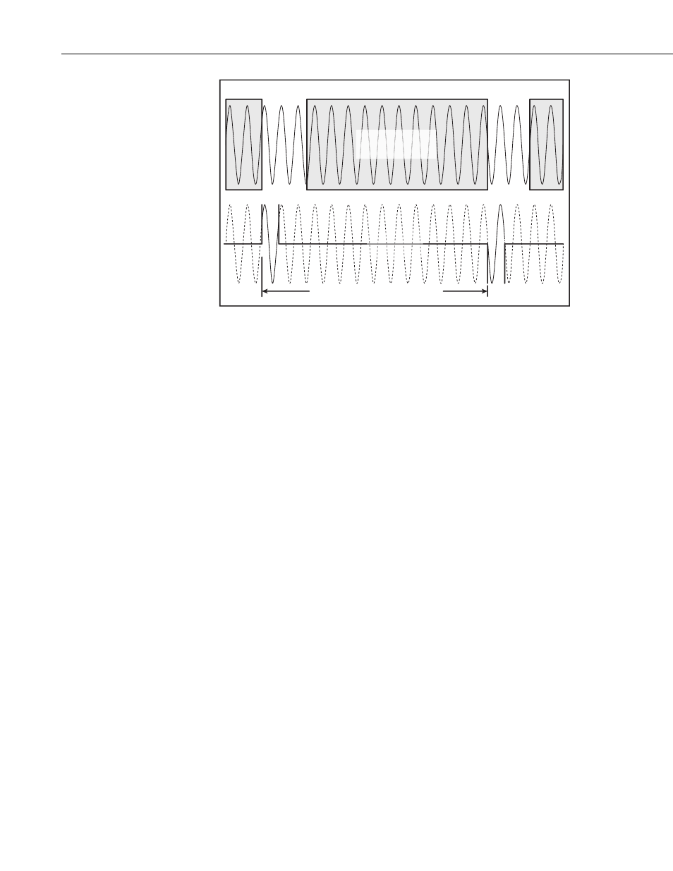
FIGURE A-1. Timing of dynamic vibrating-wire measurements
An important aspect of dynamic measurement timing is synchronizing the
process to an external timing source that is independent of the wire oscillation.
Synchronization has intrinsic benefits to the measurement quality and also
allows simultaneous sampling of multiple channels. FIGURE A-1 shows that
the datalogger sample period dictates when the excitations are introduced and
when the frequency measurement is made. Since this sample period is
independent of the wire motion, the excitation may begin at any point in the
phase of the oscillation. When measuring single-coil sensors, inclusion of the
excitation in the measurement can skew the measured frequency and result in
increased noise and a diminished dynamic response. The remedy to excitation
noise is synchronization, which guarantees that the frequency measurement
never overlaps the excitation window. The multi-channel simultaneity enabled
by time-synchronization is another important benefit when correlating
measurements from multiple sensors. Time-synchronized excitation control is
a key differentiator between this approach and other auto-resonant, coil-
excitation methods.
A.1.1 Dynamic and Static Frequencies
CDM-VW300 series analyzers output a dynamic-frequency value for each
sensor at the rates of 20, 50, 100, 200, or 333.3 Hz. A static frequency is given
once each second. The same multiplier and offset apply to both the static and
dynamic frequency outputs.
Since only a few cycles of the wire are sampled each time a dynamic reading is
made (less than 50 ms, 20 ms, or 10 ms is available for sampling, depending on
the dynamic sample frequency used), the resolution in the spectrum is larger
(coarser) than the spectral resolution obtained when using all of the data
captured during a one-second period. As a result, there can occasionally be
noise frequencies that end up in the same FFT (Fast Fourier Transform) bin as
the signal of interest, causing measurement error. To detect such conditions, a
static, one-second frequency is provided by the analyzer. This finer resolution
reading can be examined to detect and respond to cases such as those described
above.
A-2