4 laboratory mode, 5 field mode, Laboratory mode – Campbell Scientific CDM-VW300 Series Dynamic Vibrating-Wire Analyzer System User Manual
Page 15: Field mode, Outputs, 5. laboratory-mode measurement system diagram
CDM-VW300 Series Dynamic Vibrating-Wire Analyzers
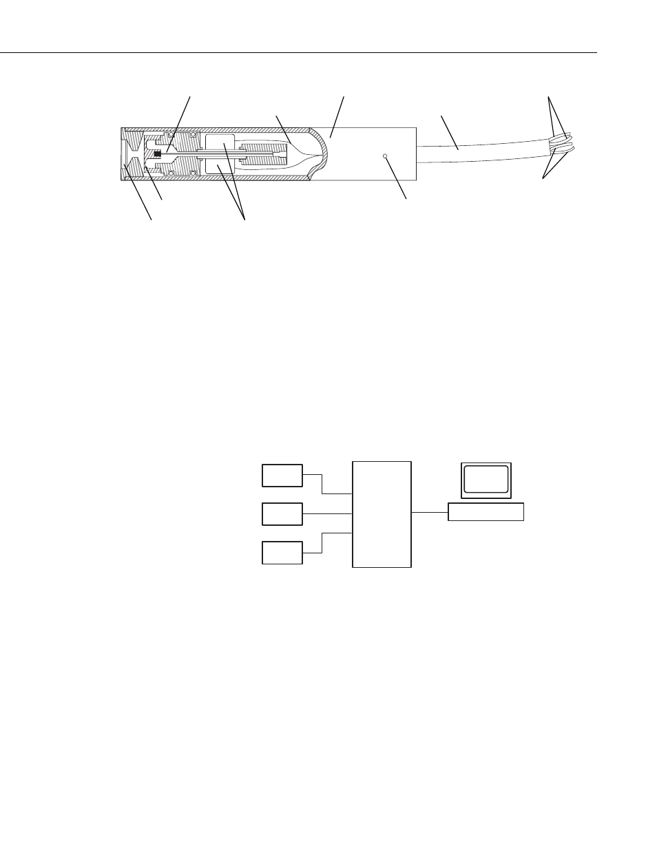
Vibrating Wire
Thermistor
Stainless Steel Housing
4-Conductor Cable
Filter
Plucking and Pickup Coils
Diaphragm
Internal Bulkhead Seal
Two Coil Outputs
Two Thermistor
Outputs
FIGURE 4-4. Single-coil vibrating-wire sensor including coil and
thermistor outputs
4.4 Laboratory Mode
Laboratory mode allows for examination and validation of specific
measurements types without a datalogger, such as might occur before field
deployment. As shown in FIGURE 4-5, a connection is made from the CDM-
VW300 to a personal computer using a USB cable. Campbell Scientific
DVWTool software on the PC enables observation of sensor outputs and
configuration of the CDM-VW300 to measure sensors. Specific procedures
can be found in Section 6.1.2, Laboratory-Mode Installation Procedure.
Vibrating-Wire
Sensors
CDM-
VW300
PC
DVWTool
FIGURE 4-5. Laboratory-mode measurement system diagram
4.5 Field Mode
Field mode is used for long-term measurement and data acquisition. As shown
in FIGURE 4-6, a connection is made from the CDM-VW300 to a Campbell
Scientific datalogger through the SC-CPI interface. A Campbell Scientific
datalogger with a customized CRBasic program configures, controls, and
collects data from the CDM-VW300. Specific installation procedures are
found in Section 6.2.2, Field-Mode Installation Procedure.
5