Ap200 system enclosure – Campbell Scientific AP200 CO2/H2O Atmospheric Profile System User Manual
Page 43
AP200 CO
2
/H
2
O Atmospheric Profile System
Insert and connect a second length of heater cable for the next intake assembly.
Continue this “daisy chain” from one intake assembly to the next until all of
the intake assemblies are connected as shown in FIGURE 5-16. Intake
assemblies will accommodate a third heater power cable that may be used to
branch off to another intake assembly. This may be useful if the intake
assemblies are mounted on two or more towers.
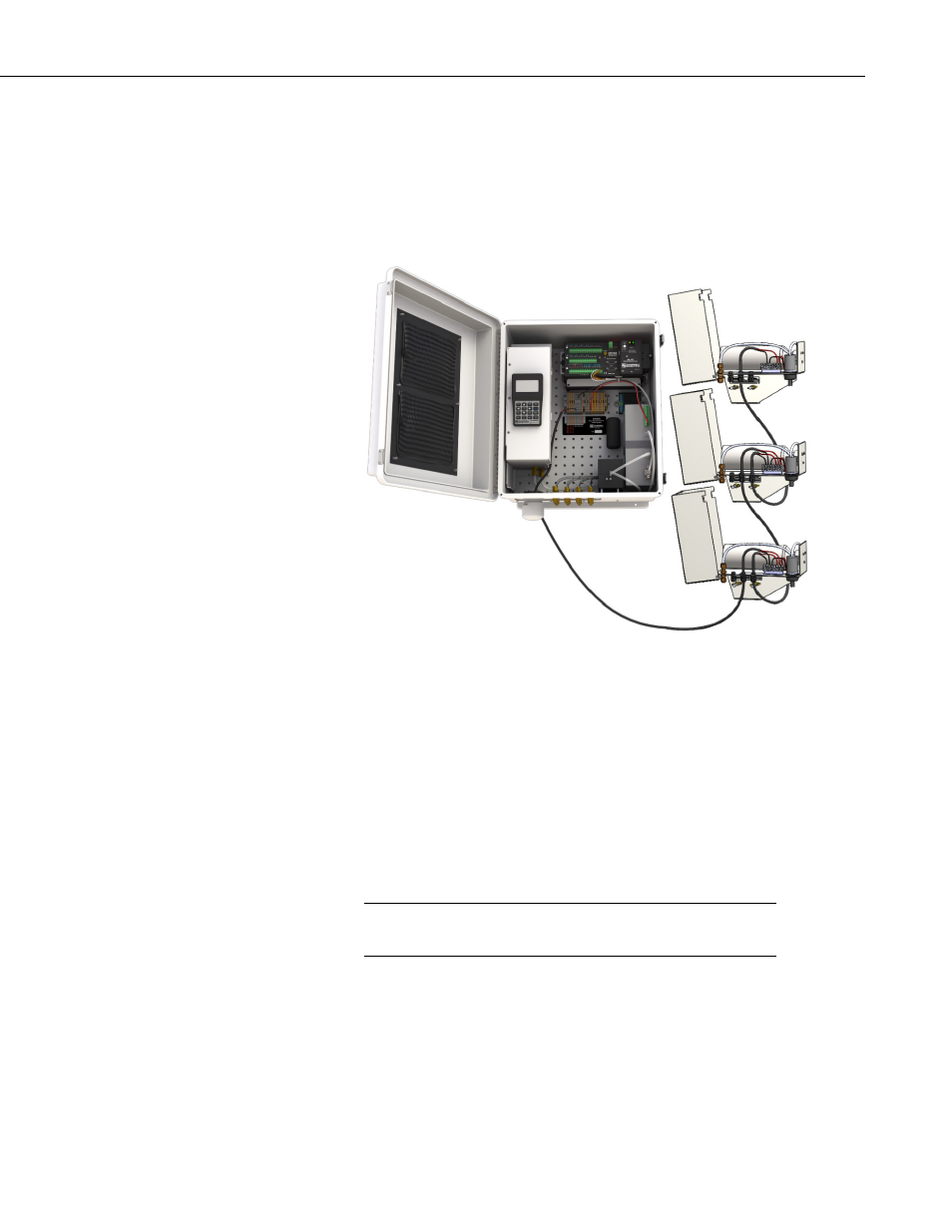
FIGURE 5-16. Three intake assemblies with heater cables daisy
chained to the AP200 system enclosure
To check the intake heater wiring, temporarily disconnect the heater cable from
the AP200 system enclosure and measure the resistance between the red and
black wires. A hand-held digital multimeter works well for this. Each heater
has a resistance of approximately 560 ohms and should be wired in parallel.
The nominal resistance will be 560 divided by the number of heaters. TABLE
5-1 shows the nominal equivalent resistance for 4 through 8 intake heater wired
in parallel. It also gives the acceptable range, which accounts for the 5%
tolerance on the resistance of each heater. If the resistance is outside this range
it is likely there is a problem with the connections or with a heater.
The resistance of the cable is small enough that it can generally
be ignored.
NOTE
31