2 ap200 enclosure, 3 intake assemblies, Ap200 enclosure – Campbell Scientific AP200 CO2/H2O Atmospheric Profile System User Manual
Page 33: Intake assemblies, Enclosure on ut30 tower
AP200 CO
2
/H
2
O Atmospheric Profile System
•
Large pole (4.0-in to 10.0-in diameter)
•
No mounting bracket
Consult the ENC10/12, ENC12/14, ENC14/16, ENC16/18 Instruction Manual,
available at
for details on mounting bracket options.
5.1.2 AP200 Enclosure
Mount the AP200 system enclosure where it can be accessed easily to retrieve
data from the CF cards on the datalogger. The AP200 system enclosure is
similar to the ENC16/18 enclosure, and it has the same mounting options
available. Consult the ENC10/12, ENC12/14, ENC14/16, ENC16/18
Instruction Manual, available at
www.campbellsci.com
, for mounting details.
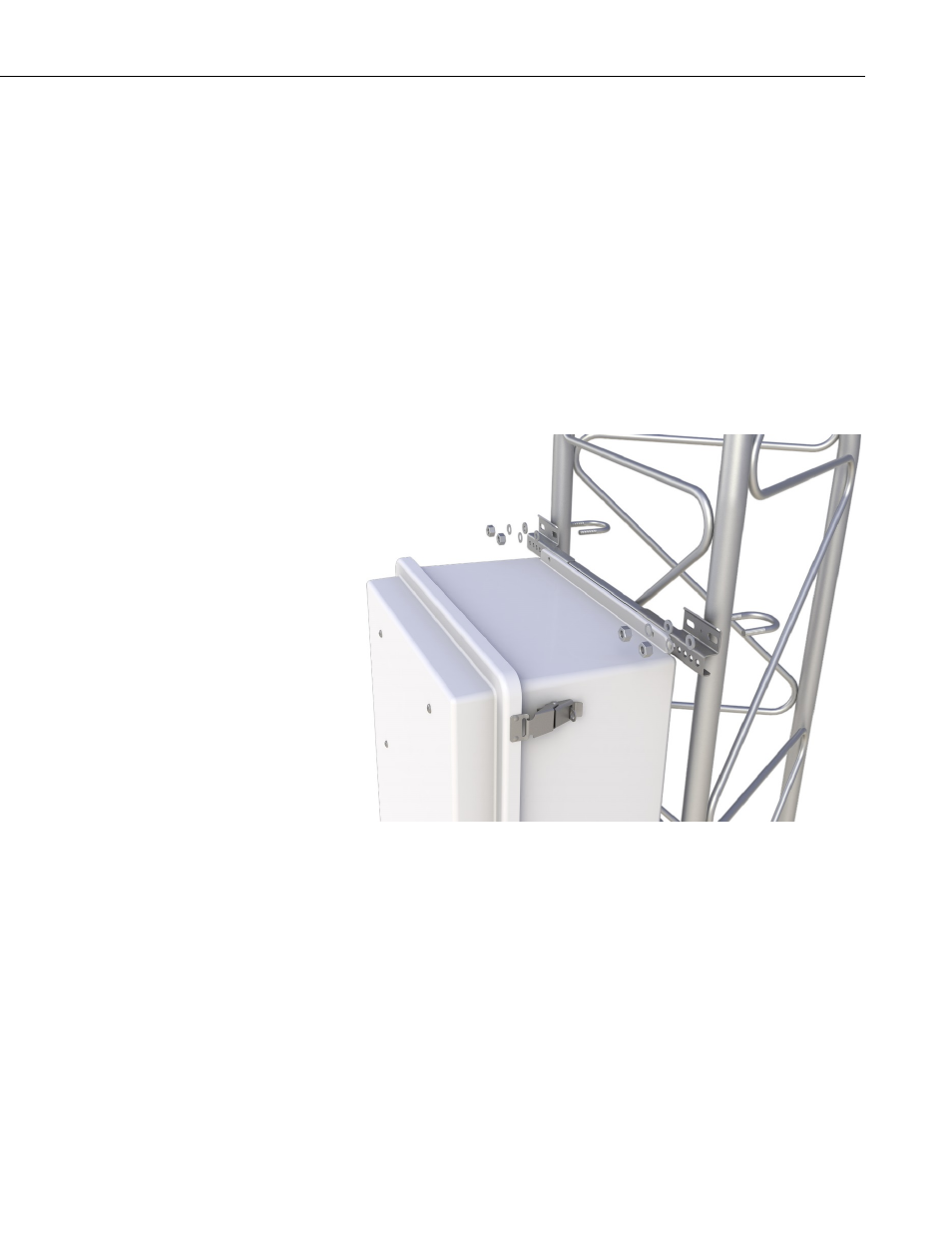
Typical installation of an AP200 system enclosure on a UT30 tower is shown
FIGURE 5-1. Installation (showing mounting hardware) of AP200
system enclosure on UT30 tower
Open the sealed bag containing the desiccant packs and humidity card. Place
two of the desiccant packs and the humidity indicator card in the mesh pocket
in the enclosure door to desiccate the inside of the enclosure. Reseal the
remaining two desiccant packs in the bag to use later.
5.1.3 Intake Assemblies
The intake assemblies are mounted at the desired air sampling positions. They
can be mounted on vertical pipes of 1.3-cm (0.5-in) to 5.1-cm (2.0-in)
diameter. The orientation of the intake assembly mounting clip must be
reversed to accommodate this range of diameters. For mounting the intake
21