8 cm – Campbell Scientific AP200 CO2/H2O Atmospheric Profile System User Manual
Page 34
AP200 CO
2
/H
2
O Atmospheric Profile System
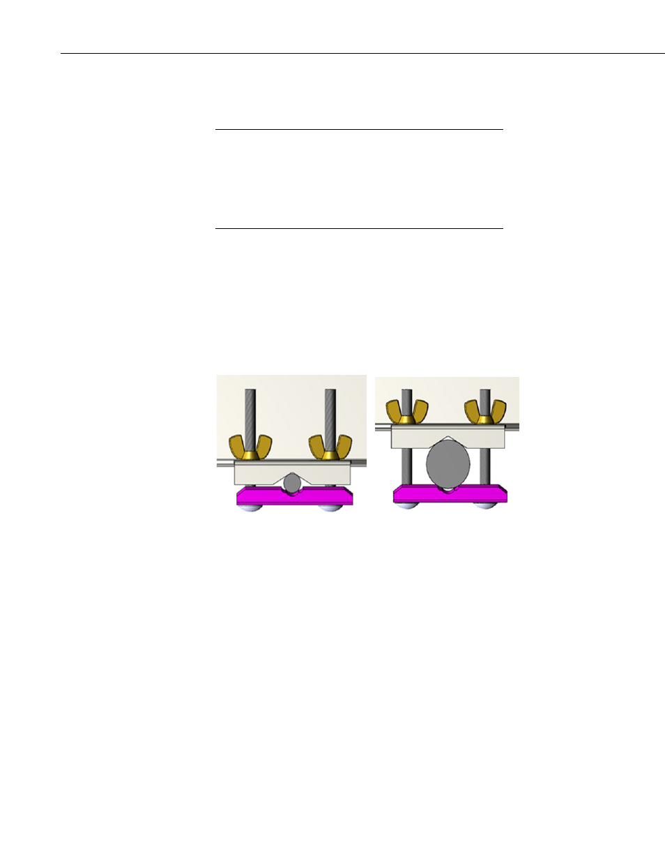
assembly on smaller pipes, orient the mounting clips with their notches toward
the pipe, as shown it FIGURE 5-2. For larger pipes, orient the mounting clips
with their notches away from the pipe, as shown in FIGURE 5-3.
Orienting the mounting clip with its notch against the mounting
pipe will help to prevent rotation of the intake assembly, which
can happen for small-diameter pipes. For larger pipe diameters,
greater than approximately 3.9 cm (1.5 in), it may become
difficult to install the intake assembly because of the length of
the bolts. Reversing the clip allows it to fit on a larger-diameter
pipe.
In some mounting situations it may be easier to access the wing nuts if they are
on the other side.
Loosen the wing nuts but do not remove them completely to avoid the risk of
dropping them. Place the assembly against the vertical support, swing the
bracket around the back of the vertical support, slide the bolt into the slot and
hand tighten the wing nuts. A typical installation of an AP200 intake assembly
on pipes of differing diameters is shown in FIGURE 5-4.
FIGURE 5-2. Mounting clip orientation for pipe diameters between 1.3
and 3.8 cm
NOTE
22