2 zero and co2 span, Zero and co, Span – Campbell Scientific AP200 CO2/H2O Atmospheric Profile System User Manual
Page 37: Inlets 1 – 4, 2 zero and co
AP200 CO
2
/H
2
O Atmospheric Profile System
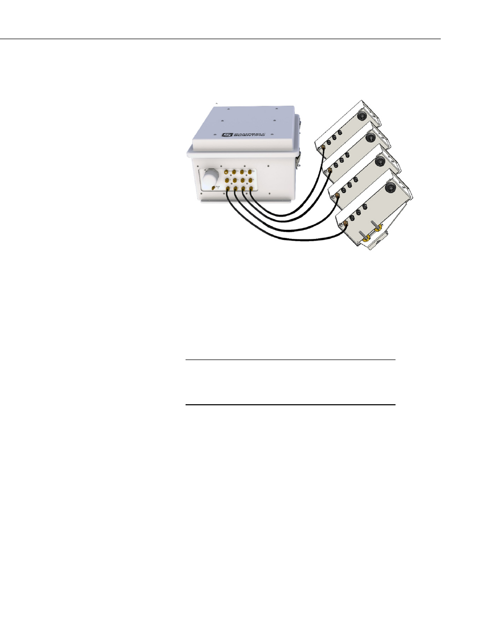
FIGURE 5-7 shows the tubing connections from the intake assemblies to the
system enclosure.
FIGURE 5-7. Tubing connections from four intake assemblies
connected to inlets 1 – 4
5.2.2 Zero and CO
2
Span
The AP200 can perform automated zero (CO
2
and H
2
O) and CO
2
span of the
IRGA. This requires the user to supply cylinders of zero air and CO
2
span gas,
with appropriate regulators.
Use high-quality gases for the zero and CO
2
span. The zero gas
must be free of significant water vapor and CO
2
. The CO
2
span
gas should have a well-known concentration of CO
2
balanced in
air (not nitrogen).
Install these cylinders in close proximity to the AP200 system enclosure. Each
cylinder must have a pressure regulator to control the outlet pressure at 0 psig
and must have a 0.25-in Swagelok
®
fitting on the outlet. Connect these fittings
to the valve module inlets using 0.25-in OD tubing, such as pn 15702.
Minimize the length of these tubes to reduce the equilibration time after the
zero or CO
2
span cylinder is selected. FIGURE 5-8 illustrates this
configuration. Refer to Appendix H, Using Swagelok
®
Fittings, for
information on installing and replacing Swagelok
®
fittings. For convenience,
Campbell Scientific can supply pre-swaged tube assemblies (pn 21823-L) for
this purpose.
NOTE
25