2 valve manifold, Valve manifold, 21. valve module and swagelok – Campbell Scientific AP200 CO2/H2O Atmospheric Profile System User Manual
Page 27: Feedthrough fittings on bottom, Of ap200 enclosure
AP200 CO
2
/H
2
O Atmospheric Profile System
The flow will also vary with ambient temperature due to the corresponding
change in air density. Higher-temperature air has lower density, which will
have lower flow (approximately 2% lower flow for a 10°C temperature
change).
The sample flow will decrease over time as particulates clog the filters.
Eventually, the flow will be reduced to the extent that it will degrade the
equilibration time after an intake is selected. As a general guideline, the filters
should be replaced when the flow decreases by 25%. The filters will normally
last a few months, but will require more frequent changes in dirty conditions.
The intake assembly has been designed with two separate elements intended to
prevent condensation. First, the rain diverter has a small heater (0.25 W at 12
Vdc) to warm the air sample to approximately 10°C above ambient
temperature before reaching the filter and orifice. This prevents condensation
on surfaces upstream of the orifice. Second, the flow path downstream of the
orifice is kept at reduced pressure (typically 35 kPa below ambient pressure) to
prevent condensation.
The intake assembly includes a mixing volume to dampen fluctuations in the
CO
2
and H
2
O concentrations. Assuming the nominal dependence of pressure
and flow on elevation, and a 35-kPa pressure drop at the orifice, the mixing
volume residence time will vary from 2.0 min at sea level to 1.5 min at 3000
m. This residence time is similar to the time to cycle through all of the intakes
(1 to 2 min, depending on the number of intakes used). This ensures that a
transient change in atmospheric CO
2
or H
2
O concentration will be measured by
each of the intakes, regardless of when it occurs during the valve-switching
cycle.
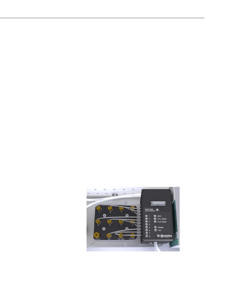
4.2.2 Valve Manifold
The valve manifold is mounted on the bottom of the AP200 system enclosure.
It has LEDs to show which valve is active and the state of the heater and fan.
It has stainless steel tubes that connect the manifold to Swagelok
®
feedthrough
fittings on the bottom of the enclosure as shown in FIGURE 4-21.
FIGURE 4-21. Valve module and Swagelok
®
feedthrough fittings on
bottom of AP200 enclosure
15