3internal circuit schematic – Horner APG SmartStack I/O HE-MIX902* User Manual
Page 3
MAN0292-08
10 NOV 2006
PAGE 3
MIX902
This Data Sheet is published individually & also as a part of the SmartStack Supplement (SUP0246-05).
Information is subject to change without notice. SmartStack is a trademark of Horner APG, LLC.
2.2
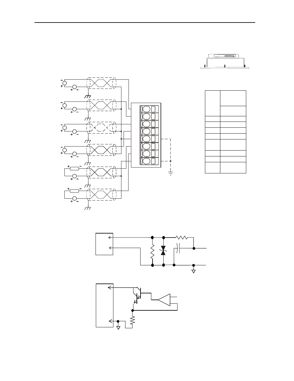
Analog Input / Output (P2)
3
INTERNAL CIRCUIT SCHEMATIC
Specification for transient voltage suppressors (transorbs) used on output circuitry is 30V, 300W.
Analog
In and
Out
Pin
MIX902
P2
I1 Input
1
I2 Input
2
I3 Input
3
I4 Input
4
C2 Input
Common
Q1 Output
1
Q2 Output
2
C3 Output
Common
OCS
Top View – Shows
Corresponding I/O Pin
*
I/O Connector
I1
C
To
Controller
SmartStack Analog Input
Field
Side
200Ω
I/O Connector
From
Controller
Q1
C
+
-
SmartStack Analog Out
Field
Side
I1
I4
I2
C2
Q2
I3
Q1
C3
4-20mA
TRANSMITTER
LOOP POWER
4-20mA
TRANSMITTER
LOOP POWER
4-20mA
TRANSMITTER
LOOP POWER
4-20mA
TRANSMITTER
LOOP POWER
LOOP POWER
LOOP POWER
LOAD
LOAD
001MIX005
*