13 serial line terminations, 14 protocol configuration, 15 address configuration – Videotec ULISSE COMPACT User Manual
Page 25
Instruc
tions manual - English - EN
25
MNVCUCZ_1351_EN
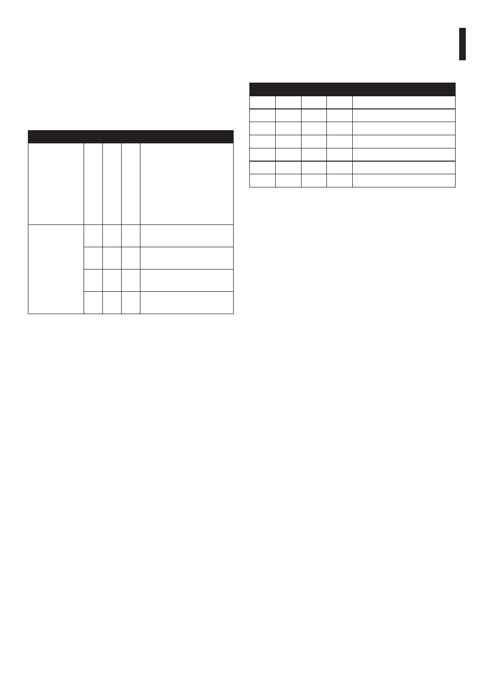
7.1.13 Serial line terminations
To set the serial line terminations operate on DIP
1.
The board has two DIP switches used to configure the
serial line terminations (120 Ohm) (Tab. 7, page 25).
Every peripheral that is situated at the end of a line
must be terminated using the appropriate dip-switch
in order to prevent signal reflection and distortion.
SERIAL LINE TERMINATIONS (DIP 1)
Description
SW 1-2-3-4-5-6
SW 7
SW 8
Configur
ation
Serial line
terminations
–
–
ON RS-485-2 line, termination
enabled
–
–
OFF RS-485-2 line, termination
disabled
–
ON –
RS-485-1 line, termination
enabled
–
OFF –
RS-485-1 line, termination
disabled
Tab. 7
7.1.14 Protocol configuration
To set the protocol operate on DIP 3.
Video positioning systems of the P&T can be
controlled by a range of protocols.
PROTOCOL CONFIGURATION (DIP 3)
SW 1 SW 2 SW 3 SW 4 Configuration
ON
OFF
ON
OFF
PANASONIC
OFF
OFF
ON
OFF
ERNITEC
OFF
ON
OFF
OFF
SENSORMATIC
ON
OFF
OFF
OFF
PELCO D
OFF
OFF
OFF
OFF
VIDEOTEC MACRO
OFF
ON
ON
OFF
NETWORK
Tab. 8
7.1.15 Address configuration
To set the address operate on DIP 2.
It is possible to set the pan & tilt address: from 1 to
1023. Binary code is used to select the address, using
the dip-switches (A Appendix - Address table, page
70).