7 alarm and relay connections – Videotec ULISSE COMPACT User Manual
Page 19
Instruc
tions manual - English - EN
19
MNVCUCZ_1351_EN
7.1.7 Alarm and relay connections
The Alarm Board, if present, is located on the base of
the unit, as shown in the figure here below.
Fig. 21
It features six alarm contacts and two output relays
with clean contact. There are two recognized alarms
type:
• Clean contact alarm (5 alarm inputs available).
• Energised alarm (1 alarm input available, only for
the control of the washing liquid level).
Fig. 22
CONNECTION OF THE ALARM INPUTS, OF THE
TWILIGHT SWITCH AND OF THE RELAYS
Terminal
Description
W, G
Voltage-controlled liquid level alarm, referred
to G
A1, A2, A3,
A4, A5* and G
Self-powered alarm inputs referred to G
R1A-R1B and
R2A-R2B
Clean output contacts, can be activated by
alarm or by user control
Tab. 3
* It can be used as input for the dusk switch (not sup-
plied) used to switch on the LED illuminator.
All alarms have an approximate reach of 200m, which
can be obtained using an unshielded cable with a
minimum section of 0.25mm² (AWG 24).
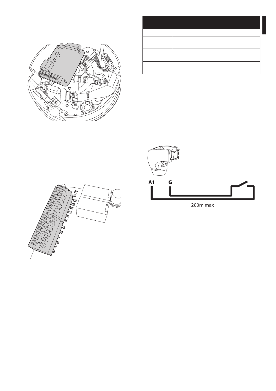
7.1.7.1 Connecting an alarm with clean
contact (dry contact)
For a clean contact alarm (alarms A1, A2, A3, A4 and
A5), carry out tthe connections as shown in figure.
Dry contact
Fig. 23
The alarm switch can be NO (normally open) or NC
(normally closed).
For further details on configuring and using the
alarms, refer to the related chapter (9.1.12.1 Alarms
Menu, page 43).