4 video cable connection, 5 telemetry line connections – Videotec ULISSE COMPACT User Manual
Page 17
Instruc
tions manual - English - EN
17
MNVCUCZ_1351_EN
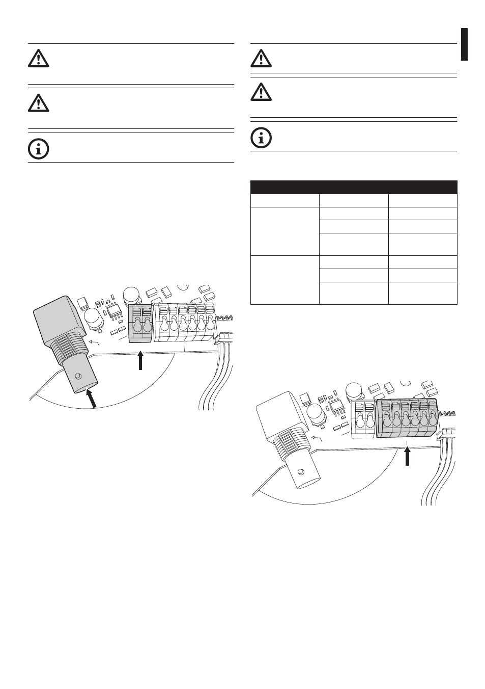
7.1.4 Video cable connection
The installation is type CDS (Cable
Distribution System), do not connect it to
SELV circuits.
In order to reduce the risk of fire, only use
cable sizes greater than or equal to 26AWG
(0.13mm²).
The content of this chapter does not apply
to the versions with digital video encoder.
The video signal is present on connectors J5 and J7 of
the board. Only use one connector.
Connector J5: Connect the screen and the central
cable to terminals GND and CVBS respectively.
Connector J7: Connect the coaxial cable to the BNC
connector (not supplied) and then connect it to
connector J7.
The terminals accept cables with sections between
1.5mm² (AWG16) and 0,5mm² (AWG30).
VIDEO OUT
J7
CVBS
J5
GND
RS485-1
SGND
A
B
RS485-2
SGND
A B
Fig. 14
7.1.5 Telemetry line connections
The installation is type TNV-1, do not
connect it to SELV circuits.
In order to reduce the risk of fire, only use
cable sizes greater than or equal to 26AWG
(0.13mm²).
The content of this chapter does not apply
to the versions with digital video encoder.
The product is supplied with 2 RS-485 serial
communication lines.
TELEMETRY LINE CONNECTIONS
Serial line
Terminal
Description
RS-485-1
A (+)
RS-485 line (1)
B (-)
RS-485 line (1)
SGND
RS-485-1 line
reference
RS-485-2
A (+)
RS-485 line (2)
B (-)
RS-485 line (2)
SGND
RS-485-2 line
reference
Tab. 2
The lines can be configured in various ways according
to the positions of dip-switches 5 and 6 on the Serial
(DIP 1) of the CPU board (7.1.12 Setting of the serial
communication lines, page 23).
VIDEO OUT
J7
CVBS
J5
GND
RS485-1
SGND
A
B
RS485-2
SGND
A B
Fig. 15