2 relay connection – Videotec ULISSE COMPACT User Manual
Page 20
EN - English - I
nstruc
tions manual
20
MNVCUCZ_1351_EN
7.1.7.2 Relay connection
Relays are located inside R1A and R1B (Relay 1) and
inside R2A and R2B (Relay 2) connectors. Relays do
not have polarity and therefore both terminals A or
B of the same relay can be used, for alternating or
continuous current voltages.
RELAY CONNECTION
Terminal
Description
R1A
Relay 1, Terminal A
R1B
Relay 1, Terminal B
R2A
Relay 2, Terminal A
R2B
Relay 2, Terminal B
Tab. 4
Relays can be used for low working
voltages only (up to 30Vac or 60Vdc) and
with a maximum current of 1A. Use cables
with a section suitable for the load to be
controlled and use cables with a minimum
section of 0.25mm² (AWG 30) and maximum
section of 1.5mm² (AWG 16).
For further details on configuring and using the
relays, refer to 9.1.12.1 Alarms Menu, page 43.
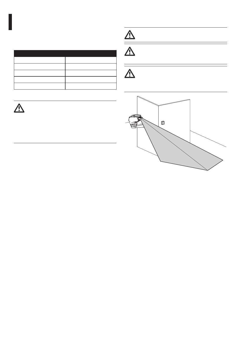
7.1.7.3 Connecting the dusk switch for the
LED illuminator
During installation do not look directly at
the illuminator while it is on.
To guarantee correct vision during the day
and the night, it is necessary to correctly set
the sensor.
The dusk switch must be positioned so that
it is not hit by the light beam coming from
the illuminator or by artificial lights (such as
road lights, car headlights, etc.).
Fig. 24