8 fixing the top unit, 9 configuration of the dip-switches – Videotec ULISSE COMPACT User Manual
Page 22
EN - English - I
nstruc
tions manual
22
MNVCUCZ_1351_EN
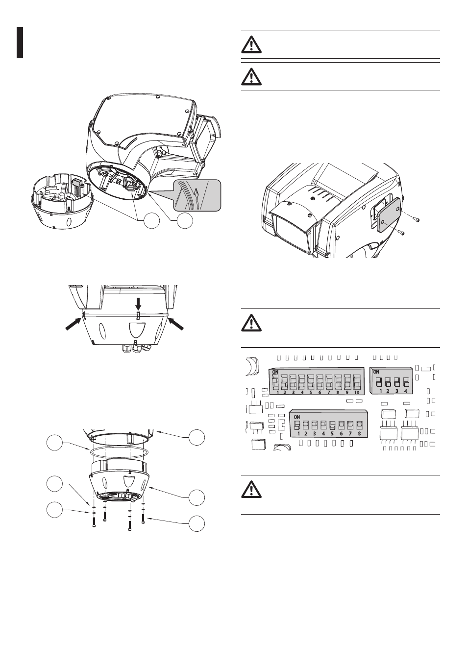
7.1.8 Fixing the top unit
Point the self-centering connector (01) of the upper
unit. Point the side set (02) so that it faces the frontal
vision of the camera. Position the upper part on the
base in the same direction shown in the figure.
01
02
Fig. 26
The side sets on the base and on the upper unit are
thus aligned in the only possible position.
Fig. 27
Fasten the upper unit (01) to the base (02) by means
of the fastening screws (03), the notched washers (04)
and the flat washers (05). Make sure that the base
gasket is in position and in good state (06).
01
02
03
04
05
06
Fig. 28
Apply a Loctite 243® type thread-locker on
the holes of the screws.
Pay attention to the fixing. Tightening
torque: 4Nm max.
7.1.9 Configuration of the dip-switches
Before powering the device it must be configured
correctly by setting the dip-switches inside the
configuration window. Open the hatch by undoing
the screws as shown in figure.
Fig. 29
The side sets on the base and on the upper unit are
thus aligned in the only possible position.
When the dip-switch rocker (SW) is up it
represents the value 1 (ON) while if it is
down it represents the value 0 (OFF).
DIP2
DIP3
DIP1
Fig. 30
The protocol must be set to NETWORK in
case of versions with digital video encoder (
7.1.14 Protocol configuration, page 25).