External module disassembly process, External modules disassembly flowchart – Acer 2930 User Manual
Page 53
Chapter 3
43
External Module Disassembly Process
External Modules Disassembly Flowchart
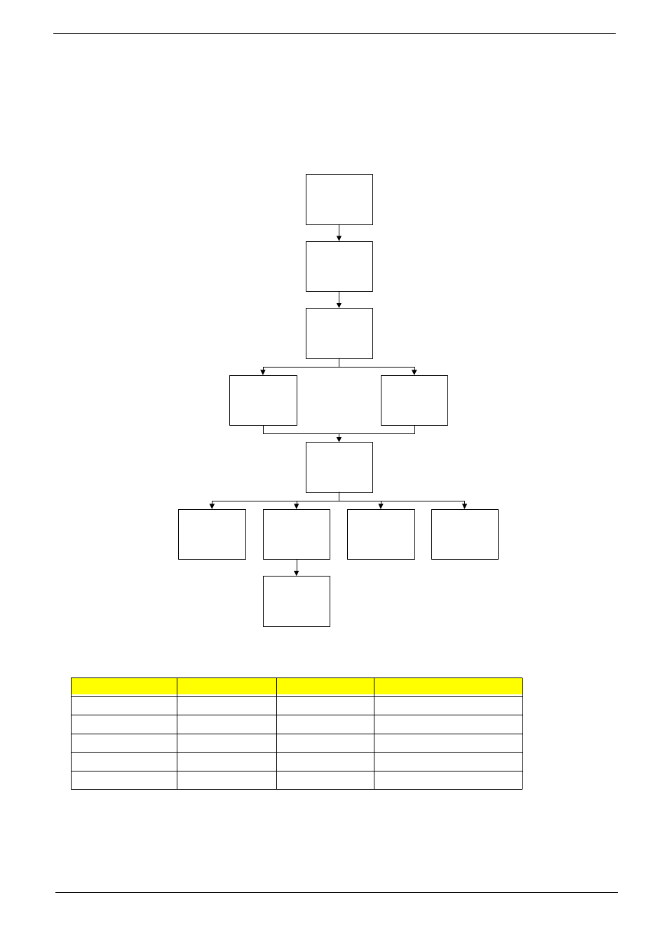
The flowchart below gives you a graphic representation on the entire disassembly sequence and instructs you
on the components that need to be removed during servicing. For example, if you want to remove the main
board, you must first remove the keyboard, then disassemble the inside assembly frame in that order.
Screw List
Step
Screw
Quantity
Part No.
WLAN Module
M2*3
2
86.ART02.001
HDD Module
M2.5*5
3
86.ART02.004
HDD Carrier
M3*3
4
86.ART02.007
ODD Module
M2.5*8
1
86.ART02.005
ODD Bracket
M2*3
2
86.ART02.001
Remove
Lower Covers
Remove
Express Dummy
Card
Disconnect power
and signal cables
from system
Remove Battery
Turn off system
and peripherals
power
Remove
SD Dummy Card
Remove
DIMM Modules
Remove
ODD Module
Remove
WLAN Board
Remove
HDD Module
Remove
WLAN Antenna
- Aspire 5741ZG (2345 pages)
- Aspire 5741ZG (313 pages)
- Extensa 7230 (86 pages)
- TravelMate 5330 (14 pages)
- AOD257 (1810 pages)
- AO753 (374 pages)
- AO533 (4 pages)
- AOD255 (299 pages)
- AO522 (1810 pages)
- Aspire V5-531G (2484 pages)
- Aspire EC-471G (10 pages)
- Aspire M3-581TG (3478 pages)
- Aspire M3-581TG (11 pages)
- Aspire M3-581PTG (10 pages)
- Aspire 8950G (378 pages)
- Aspire EC-471G (11 pages)
- Aspire V5-571PG (3604 pages)
- Aspire E1-571 (308 pages)
- Aspire E1-521 (11 pages)
- Aspire S5-391 (111 pages)
- Aspire S5-391 (11 pages)
- Aspire M5-581TG (10 pages)
- Aspire M5-581TG (11 pages)
- Aspire V3-471G (362 pages)
- Aspire V3-471G (11 pages)
- Aspire M5-481TG (11 pages)
- Aspire 9420 (109 pages)
- Aspire 9520 (123 pages)
- 3280 (106 pages)
- 4600 (128 pages)
- Aspire 1300 (96 pages)
- 4330 (198 pages)
- TravelMate 3250 (98 pages)
- 1450 (99 pages)
- 2420 (108 pages)
- 310 (2 pages)
- 310 (130 pages)
- 3690 (123 pages)
- 5010 (113 pages)
- 3250 (124 pages)
- 5560 (112 pages)
- 5230 (176 pages)
- 420 series (78 pages)
- 3000 (109 pages)
- 3200 Series (90 pages)