Out ), Utput, Arameters – Red Lion PAX2C User Manual
Page 17: Dgtl ), Dgtl, Slct, Asgn, Lgic, Asel, Cyct
17
O
uTpuT
p
arameTers
(Out)
OUTPUT SELECT
dGtL
AnLG
Select the Digital or Analog output to be programmed. The Analog
output selection only appears if an analog output and/or digital output
plug-in card is installed in the meter. When there is no output card
installed, “No Card” will be displayed on the display when trying to
enter the Output Configuration.
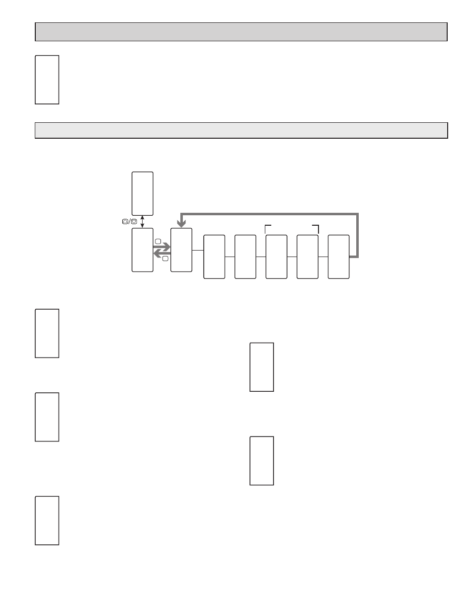
Out
INP
dGtL
Output
Select
Output
Assignment
Alarm Logic
Assignment
Alarm Mask
Assignment
Output
Cycle Time
F1
F2
P
D
Pro
N O
Pro
O u t
Out
P2C
d G t L
SLCt
P2C
O u t n
ASGN
On
H E A t
LGIC
On
S N G L
ASEL
Un
N O
An
CYCt
INP
2 . 0
SEC
Available when
ASGN
= ALr
n
'LJLWDO2XWSXW1XPEHU
To have digital output capabilities, a digital output Plug-in card needs to be installed into the PAX2C (see Ordering Information). Depending on the output
card installed, there will be two or four digital outputs available.
DIGITAL OUTPUT SELECTION
Out1 Out2
Out3
Out4
Selects the digital output to be programmed. The “Outn” in the
following parameters will reflect the chosen output number. After the
chosen output is completely programmed, the display returns to the
Output Select menu. Repeat steps for each output to be programmed.
The number of outputs available is digital output card (PAXCDS)
dependent (2 or 4).
DIGITAL OUTPUT ASSIGNMENT
NONE
HEAt
COOL
ALr
MAN
This selection is used to assign the controller’s digital outputs to
various internal values or conditions. It is possible to assign the same
properties to more than one output.
NONE
= Digital Output is disabled
HEAt
= Heat Output Power
COOL
= Cool Output Power
ALr
= Alarm
MAN
= Manual Control Mode
ALARM LOGIC MODE
SNGL And
Or
The PAX2C supports three different modes when an output is
assigned as an alarm:
SNGL
= Any single alarm. Selecting YES to any selection
will change other alarm selections to NO.
And
= Allows multiple alarms to be mapped to an output
using AND Boolean logic. For example: If AL1 and
AL2 are active, the output will energize.
Or
= Allows multiple alarms to be mapped to an output
using OR Boolean logic. For example: If AL1 or
AL2 are active, the output will energize.
ALARM MASK ASSIGNMENT
NO
YES
Selects the alarms to be logically combined per the Alarm Logic
Mode selection. Any alarms configured as “YES” will be used in the
Boolean logic calculation. If the Alarm Logic Mode is assigned as
Single (SNGL), only one alarm may be selected at a time.
Basic Mode: 4 Alarms Max
Advanced Mode: 16 Alarms Max
DIGITAL OUTPUT CYCLE TIME
0.0
to
60.0
seconds
The Cycle Time value is the sum of a time-proportioned output’s
on and off cycles. With time proportional outputs, the percentage of
output power is converted into output on time of the cycle time value
eg. if the controller’s algorithm calls for 65% power, and has a Cycle
Time of 10 seconds, the output will be on for 6.5 seconds and off for
3.5 seconds. A Cycle Time equal to, or less than, one-tenth of the process time
constant is recommended.
This parameter is only available when the digital output assignment is
configured as HEAt or COOL.
SLCt
P2C
Outn
ASGN
On
HEAt
LGIC
On
SNGL
ASEL
Un
NO
An
CYCt
INP
2.0
SEC
d
igiTal
O
uTpuT
p
arameTers
(dGtL)