Type, Root, Rate – Red Lion PAX2C User Manual
Page 13: Dcpt, Ofst, Fltr, Pnts, Anlg ), Inpt, Styl
13
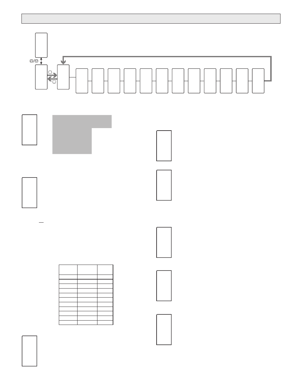
PROCESS INPUT TYPE
250 uA
2 U
1k RES
tc-r
r392
2.5 mA
10 U
10k RES
tc-S
r672
25 mA
25 U
tc-t
tc-b
r427
250 mA
100 U
tc-E
tc-n
2 A
200 U
tc-J
tc-C
250 mU
100 RESs
tc-k
r385
Shaded selections indicate the available process input types. Select the
desired input type.
SQUARE ROOT
YES
NO
This parameter allows the unit to be used in applications in which
the measured signal is the square of the PV. This is useful in
applications such as the measurement of flow with a differential
pressure transducer.
Example: It is necessary to square root linearize the output of a differential
pressure transmitter to indicate and control flow. The defining equation is F
= 278 ÖΔP , where ΔP = 0 - 500 PSI, transmitted linearly by a 4 - 20 mA
transducer. At full flow rate ( ΔP = 500 PSI), the flow is 6216 ft
3
/h. The
following scaling information is used with the controller:
dCPt
= 0
INPt1
= 4.00 mA
Root
= YES
dISP2
= 6216 ft
3
/hr
dISP1
= 0 ft
3
/hr
INPt2
= 20.00 mA
As a result of the scaling and square root linearization, the following
represents the readings at various inputs:
Delta P
(PSI)
Transmitter
(mA)
Flow
(ft
3
/hr)
0.00
4.00
0
15.63
4.50
1099
31.25
5.00
1554
62.50
6.00
2198
125.00
8.00
3108
187.50
10.00
3807
250.00
12.00
4396
312.50
14.00
4914
375.00
16.00
5383
437.50
18.00
5815
500.00
20.00
6216
INPUT UPDATE RATE (/SEC)
5
10
20
40
Select the ADC conversion rate (conversions per second). The
selection does not affect the display update rate, however it does
affect alarm and analog output response time. The default factory
setting of 5 is recommended for most applications. Selecting a fast update rate
may cause the display to appear very unstable.
DECIMAL RESOLUTION (Display Units)
0
to
0.000
(curr/volt/ohm)
0
to
0.0
(temp)
Select desired display resolution. The available selections are
dependent on the Input Type selected
(
tYPE
)
.
ROUNDING INCREMENT
1
2
5
10
20
50
100
Rounding selections other than one, cause the Input Display to
‘round’ to the nearest rounding increment selected (ie. rounding of
‘5’ causes 122 to round to 120 and 123 to round to 125). Rounding
starts at the least significant digit of the Input Display. Remaining
parameter entries (scaling point values, setpoint values, etc.) are not automatically
adjusted to this display rounding selection.
DISPLAY OFFSET
-1999
to
9999
The display can be corrected with an offset value. This can be used
to compensate for sensor errors, errors due to variances in sensor
placement or adjusting the readout to a reference source. A value of
zero will remove the affects of offset.
DIGITAL FILTERING
0.0
to
25.0
seconds
The input filter setting is a time constant expressed in tenths of a
second. The filter settles to 99% of the final display value within
approximately 3 time constants. This is an Adaptive Digital Filter
which is designed to steady the Input Display reading. A value of ‘0’
disables filtering.
SCALING POINTS
2
to
16
Linear - Scaling Points (2)
For linear processes, only 2 scaling points are necessary. It is
recommended that the 2 scaling points be at opposite ends of the
input signal being applied. The points do not have to be the signal
limits. Display scaling will be linear between and continue past the
entered points up to the limits of the Input Signal Jumper position. Each scaling
point has a coordinate-pair consisting of an Input Value (INPt n) and an
associated desired Display Value (dISP n).
tYPE
INP
2
U
Root
INP
NO
rAtE
INP
20
SPS
dCPt
INP
0.0
rnd
INP
0.1
OFSt
INP
0.0
FLtr
INP
1.0
SEC
PNtS
INP
2
Input
Range
Enable
Square
Root
Input
Rate
Display
Decimal
Point
Display
Rounding
Display
Offset
Value
Filter
Setting
Scaling
Points
F1
F2
P
D
Pro
N O
Pro
I N P t
INPt
P2C
A n L G
tYPE
INP
2
U
Root
INP
N O
rAtE
INP
2 0
SPS
dCPt
INP
0 . O
rnd
INP
0 . 1
OFSt
INP
0 . 0
FLtr
INP
1 . O
SEC
PNtS
INP
2
Scaling
Style
StYL
INP
K E Y
Input n
Value
INPt
INP
0 . 0
1
Display n
Value
dISP
INP
0 . O
1
Enable
Scaling
List
SLSt
INP
N O
This section details the programming for the analog input.
a
nalOg
i
npuT
p
arameTers
: p
rOCess
m
Ode
(AnLG)