9 module 9 - f, D-lev, Fcs pro – Red Lion PAXT User Manual
Page 29: Code, Actory, Ervice, Perations, Parameter menu
29
d-LEV
Display
Intensity Level
PAR
9-FCS
Pro
Factory
Service Code
COdE
6.9 mOdUle 9 - f
aCTOry
s
erviCe
O
peraTiOns
(
)
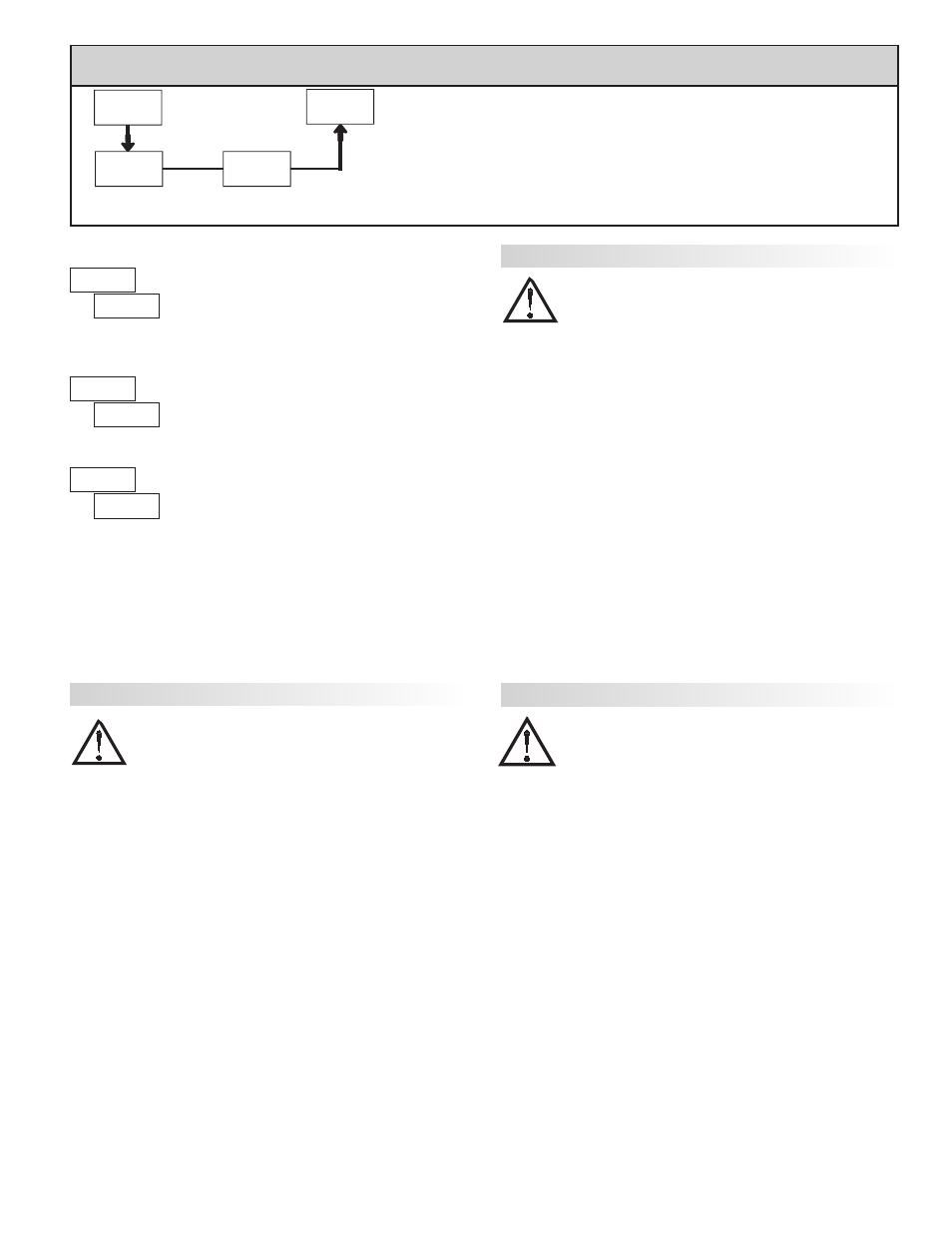
PARAMETER MENU
Enter the desired Display Intensity Level (0-15) by
using the arrow keys. The display will actively dim or
brighten as the levels are changed. This parameter also
appears in Quick Programming Mode when enabled.
DISPLAY INTENSITY LEVEL
The meter has been fully calibrated at the factory.
Scaling to convert the input signal to a desired display
value is performed in Module 1. If the meter appears to be
indicating incorrectly or inaccurately, refer to
Troubleshooting before attempting to calibrate the meter.
When recalibration is required (generally every 2 years), it should only be
performed by qualified technicians using appropriate equipment. Calibration
does not change any user programmed parameters. However, it may affect the
accuracy of the input signal values previously stored using the Apply (
)
Scaling Style.
Calibration may be aborted by disconnecting power to the meter before
exiting Module 9. In this case, the existing calibration settings remain in effect.
CALIBRATION
Before starting, verify that the Input Ranger Jumper is set for the range to be
calibrated. Also verify that the precision signal source is connected and ready.
Allow a 30 minute warm-up period before calibrating the meter.
and
PAR
can be chosen to exit the calibration mode without any changes taking place.
Then perform the following procedure:
1. Use the arrow keys to display
and press
PAR.
2. Choose the range to be calibrated by using the arrow keys and press
PAR.
3. When the zero range limit appears on the display, apply the appropriate:
- Voltage ranges: dead short applied
- Current ranges: open circuit
- Resistance ranges: dead short with current source connected
4. Press
PAR and
will appear on the display for about 10 seconds.
5. When the top range limit appears on the display, apply the appropriate:
- Voltage ranges: top range value applied (The 300 V range is the exception.
It is calibrated with a 100 V signal.)
- Current ranges: top range value
- Resistance ranges: top range value (The ohms calibration requires
connection of the internal current source through a resistance substitution
device and the proper voltage range selection.)
6. Press
PAR and
will appear on the display for about 10 seconds.
7. When
appears, press
PAR twice.
8. If the meter is not field scaled, then the input display should match the value
of the input signal.
9. Repeat the above procedure for each input range to be calibrated.
WARNING: Calibration of this meter requires a signal source with an
accuracy of 0.01% or better and an external meter with an accuracy
of 0.005% or better. Resistance inputs require a resistance
substitution device with an accuracy of 0.01% or better.
WARNING: Calibration of this meter requires a signal source with an
accuracy of 0.01% or better and an external meter with an accuracy
of 0.005% or better.
PAXD - Input Calibration
PAXH - Input Calibration
PAXP - Input Calibration
Before starting, verify that the precision signal source is connected to the
correct terminals and ready. Allow a 30 minute warm-up period before
calibrating the meter.
and
PAR can be chosen to exit the calibration mode
without any changes taking place.
Then perform the following procedure:
1. Use the arrow keys to display
and press
PAR.
2. Choose the range to be calibrated by using the arrow keys and press
PAR.
(
and
PAR can be chosen to exit the calibration mode without any changes
taking place.)
3. When the zero range limit appears on the display, apply the appropriate:
- Voltage range: dead short applied
- Current range: open circuit
4. Press
PAR and
will appear on the display for about 10 seconds.
5. When the top range limit appears on the display, apply the appropriate:
- Voltage range: 10 VDC
- Current range: 20 mADC
6. Press
PAR and
will appear on the display for about 10 seconds.
7. When
appears, press
PAR twice.
8. If the meter is not field scaled, then the input display should match the value
of the input signal.
9. Repeat the above procedure for each input range to be calibrated.
WARNING: In the PAXH, DC signals are used to calibrate the AC
ranges. Calibration of the PAXH requires a DC voltmeter with an
accuracy of 0.025% and a precision DC signal source capable of:
1. +1% of full scale, DC
2. -1% of full scale, DC
3. +100% of full scale, DC; (300 V range = +100 V calibration)
4. -100% of full scale, DC; (300 V range = -100 V calibration)
Before starting, verify the Input Range and Signal Jumpers are set for the
range to be calibrated and the Couple jumper is installed for DC. Also verify the
DC signal source is connected and ready. Allow a 30 minute warm-up period
before calibrating the meter.
and
PAR can be chosen to exit the calibration
mode without any changes taking place.
Then perform the following procedure:
1. Press the arrow keys to display
and press
PAR.
2. The meter displays
. Use the arrow keys to select the range that matches
the Signal Jumper setting. Press
PAR.
3. Apply the signal matching the meter prompt.
4. Press
PAR and
will appear on the display, wait for next prompt.
5. Repeat steps 3 and 4 for the remaining three prompts.
6. When
appears, press
PAR twice.
7. If the meter is scaled to show input signal, the Input Display should match
the value of the input signal in the Display Mode.
8. Repeat the above procedure for each range to be calibrated or to recalibrate
the same range. It is only necessary to calibrate the input ranges being used.
9. When all desired calibrations are completed, remove the external signal
source and restore original configuration and jumper settings. If AC is being
measured, continue with AC Couple Offset Calibration.
RESTORE FACTORY DEFAULTS
Use the arrow keys to display
and press
PAR.
The meter will display
and then return to
.
Press
DSP key to return to Display Mode. This will
overwrite all user settings with the factory settings.