Nstalling, Ards, Paxt jumper selection – Red Lion PAXT User Manual
Page 10
10
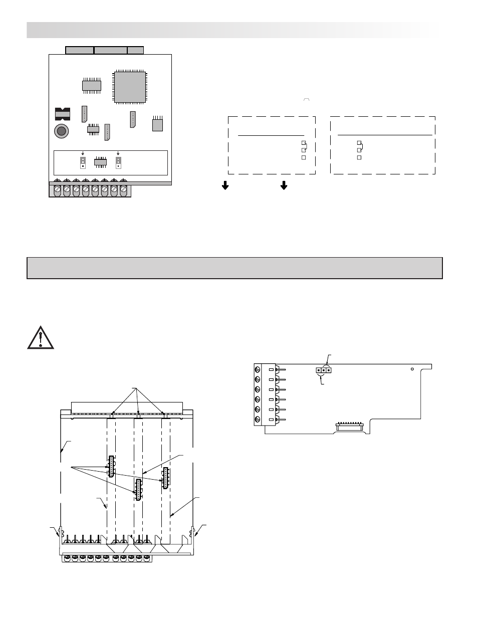
PAXT Jumper Selection
Main
Circuit
Board
JUMPER
LOCATION
JUMPER
LOCATION
USER INPUT
RTD
INPUT
USER INPUT LOGIC JUMPER
SINK
SOURCE
RTD INPUT JUMPER
REAR TERMINALS
10 ohms
100 ohms
JUMPER SELECTIONS
The
indicates factory setting.
RTD Input Jumper
One jumper is used for RTD input ranges. Select the proper range to match
the RTD probe being used. It is not necessary to remove this jumper when
not using RTD probes.
The plug-in cards are separately purchased optional cards that perform
specific functions. These cards plug into the main circuit board of the meter. The
plug-in cards have many unique functions when used with the PAX.
CAUTION: The plug-in card and main circuit board contain static
sensitive components. Before handling the cards, discharge static
charges from your body by touching a grounded bare metal
object. Ideally, handle the cards at a static controlled clean
workstation. Also, only handle the cards by the edges. Dirt, oil or
other contaminants that may contact the cards can adversely
affect circuit operation.
To Install:
1. With the meter removed from the case, locate the plug-in card connector for
the card type to be installed. The types are keyed by position with different
main circuit board connector locations. When installing the card, hold the
meter by the rear terminals and not by the front display board.
If installing the Quad sourcing Plug-in Card (PAXCDS40), set the jumper for
internal or external supply operation before continuing.
2. Install the plug-in card by aligning the card terminals with the slot bay in the
rear cover. Be sure the connector is fully engaged and the tab on the plug-in
card rests in the alignment slot on the display board.
3. Slide the meter base back into the case. Be sure the rear cover latches fully
into the case.
4. Apply the plug-in card label to the bottom side of the meter in the designated
area. Do Not Cover the vents on the top surface of the meter. The surface of
the case must be clean for the label to adhere properly.
Internal Supply
(18 V unregulated)
External Supply
(30 V )
max
3.0 i
nsTalling
p
lUg
-i
n
C
ards
Finger
Tab
Finger
Tab
Serial
Communications
Card
Setpoint
Output
Card
Alignment
Slots
Connectors
Analog Output
Card
Main
Circuit
Board
TOP VIEW