Мн о, Alternate setpoints – Red Lion PAXT User Manual
Page 24
24
Enter desired hysteresis value. See Setpoint Alarm Figures for visual
explanation of how setpoint alarm actions (balance and unbalance) are affected
by the hysteresis. When the setpoint is a control output, usually balance
hysteresis is used. For alarm applications, usually unbalanced hysteresis is used.
For unbalanced hysteresis modes, the hysteresis functions on the low side for
high acting setpoints and functions on the high side for low acting setpoints.
Note: Hysteresis eliminates output chatter at the switch point, while time delay
can be used to prevent false triggering during process transient events.
HYSTERESIS VALUE
to
to
SETPOINT VALUE
When
, the alarm is disabled (after a power up) until the trigger point is
crossed. Once the alarm is on, the alarm operates normally per the Setpoint
Action and Reset Mode.
OFF TIME DELAY
ON TIME DELAY
to
sec.
OUTPUT LOGIC
RESET ACTION
to
sec.
STANDBY OPERATION
Enter desired setpoint alarm value. These setpoint values can also be entered
in the Display Mode during Program Lock-out when the setpoint is programmed
as
in Parameter Module 3. When a setpoint is programmed as deviation or
band acting, the associated output tracks
as it is changed. The value entered
is the offset, or difference from
.
Enter the time value in seconds that the alarm is delayed from turning on after
the trigger point is reached. A value of 0.0 allows the meter to update the alarm
status per the response time listed in the Specifications. When the output logic
is
, this becomes off time delay. Any time accumulated at power-off resets
during power-up.
Enter the time value in seconds that the alarm is delayed from turning off after
the trigger point is reached. A value of 0.0 allows the meter to update the alarm
status per the response time listed in the Specifications. When the output logic
is
, this becomes on time delay. Any time accumulated at power-off resets
during power-up.
Enter the output logic of the alarm output. The
logic leaves the output
operation as normal. The
logic reverses the output logic. In
, the alarm
states in the Setpoint Alarm Figures are reversed.
Enter the reset action of the alarm output.
= Automatic action; This action allows the alarm output to automatically
reset off at the trigger points per the Setpoint Action shown in Setpoint Alarm
Figures. The “on” alarm may be manually reset (off) immediately by a front
panel function key or user input.The alarm remains reset off until the trigger
point is crossed again.
= Latch with immediate reset action; This action latches the alarm
output on at the trigger point per the Setpoint Action shown in Setpoint Alarm
Figures. Latch means that the alarm output can only be turned off by front
panel function key or user input manual reset, serial reset command or meter
power cycle. When the user input or function key is activated (momentary or
maintained), the corresponding “on” alarm output is reset immediately and
remains off until the trigger point is crossed again. (Previously latched alarms
will be off if power up Display Value is lower than setpoint value.)
= Latch with delay reset action; This action latches the alarm output
on at the trigger point per the Setpoint Action shown in Setpoint Alarm
Figures. Latch means that the alarm output can only be turned off by front
panel function key or user input manual reset, serial reset command or meter
power cycle. When the user input or function key is activated (momentary or
maintained), the meter delays the event until the corresponding “on” alarm
output crosses the trigger off point. (Previously latched alarms are off if
power up Display Value is lower than setpoint value. During a power cycle,
the meter erases a previous Latch 2 reset if it is not activated at power up.)
Enter the probe burn-out action. In the event of a temperature probe failure,
the alarm output can be programmed to go on or off.
SETPOINT ANNUNCIATORS
PROBE BURN-OUT ACTION (PAXT ONLY)
Alternate Setpoints
An Alternate list of setpoint values can be stored and recalled as needed. The
Alternate list allows an additional set of setpoint values. (The setpoint numbers
nor rear terminal numbers will change in the Alternate list.) The Alternate list
can only be activated through a function key or user input programmed for
in Module 2. When the Alternate list is selected, the Main list is stored and
becomes inactive. When changing between Main and Alternate, the alarm state
of Auto Reset Action alarms will always follow their new value. Latched “on”
alarms will always stay latched during the transition and can only be reset with
a user input or function key. Only during the function key or user input
transition does the display indicate which list is being used.
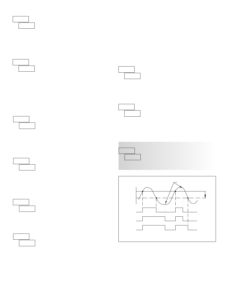
ALARM
STATE
OFF
ON
Hys
SP
OFF
ON
OFF
OFF
ON
OFF ON
OFF
OFF
ON
OFF
ON
OFF
MANUAL
RESET
SP - Hys
( Auto)
(LAtC1)
(LAtC2)
м
н
о
Setpoint Alarm Reset Actions
The
mode disables display setpoint annunciators. The
mode
displays the corresponding setpoint annunciators of “on” alarm outputs. The
mode displays the corresponding setpoint annunciators of “off” alarms
outputs. The
mode flashes the corresponding setpoint annunciators of
“on” alarm outputs.