Paxp input signal wiring, 5 am p comm, Paxh input signal wiring – Red Lion PAXT User Manual
Page 12
12
12
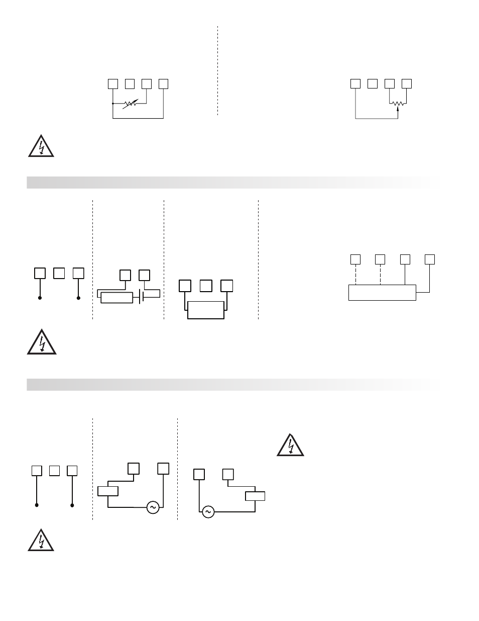
Resistance Signal
(3 wire requiring
excitation)
Terminal 3: Resistance
Terminal 5: Resistance
Terminal 6: Jumper to
terminal 3
Excitation Jumper:
1.75 mA REF.
3
4
5
6
10K MAX.
CURRENT
VOLT/OH
M
+EXCITATIO
N
COMM.
1.75 mA
REF.
Potentiometer Signal
(3 wire requiring excitation)
Terminal 3: Wiper
Terminal 5: Low end of pot.
Terminal 6: High end of pot.
Excitation Jumper: 2 V REF.
Input Range Jumper: 2 Volt
Module 1 Input Range: 2 Volt
Note: The Apply signal scaling style
should be used because the signal
will be in volts.
3
4
5
6
Rmin=1KΩ
CURRENT
VOLT/OH
M
+EXCITATIO
N
COMM.
2V REF.
2V
INPUT
Current Signal
(self powered)
Terminal 4: +ADC
Terminal 5: -ADC
Voltage Signal
(self powered)
Terminal 3: +VDC
Terminal 5: -VDC
Current Signal (2 wire
requiring excitation)
Terminal 4: -ADC
Terminal 6: +ADC
3
4
5
+
-
10 VDC MAX.
20 mA
10
V
COMM.
PAXP INPUT SIGNAL WIRING
Current Signal (3 wire
requiring excitation)
Terminal 4: +ADC (signal)
Terminal 5: -ADC (common)
Terminal 6: +Volt supply
Voltage Signal (3 wire
requiring excitation)
Terminal 3: +VDC (signal)
Terminal 5: -VDC (common)
Terminal 6: +Volt supply
4
5
+
-
20 mA DC MAX.
20 mA
COMM.
LOAD
3
4
5
6
20 mA
10
V
+24 V EXC
.
COMM.
+Vs
3 WIRE TRANSMITTER
COMM.
Iout
Vout
4
5
6
CURRENT
+24
V EX
C.
COMM.
2 WIRE
TRANSMITTER
-
+
+24V
CAUTION: Sensor input common is NOT isolated from user input common. In order to preserve the safety of the meter application, the sensor input
common must be suitably isolated from hazardous live earth referenced voltages; or input common must be at protective earth ground potential. If not,
hazardous live voltage may be present at the User Inputs and User Input Common terminals. Appropriate considerations must then be given to the
potential of the user input common with respect to earth common; and the common of the isolated plug-in cards with respect to input common.
CAUTION:
1. Where possible, connect the neutral side of the signal (including current shunts) to the input common of the meter. If the input signal is sourced from
an active circuit, connect the lower impedance (usually circuit common) to the input signal common of the meter.
2. For phase-to-phase line monitoring where a neutral does not exist, or for any other signal input in which the isolation voltage rating is exceeded, an isolating potential
transformer must be used to isolate the input voltage from earth. With the transformer, the input common of the meter can then be earth referenced for safety.
3. When measuring line currents, the use of a current transformer is recommended. If using external current shunts, insert the shunt in the neutral return line. If the
isolation voltage rating is exceeded, the use of an isolating current transformer is necessary.
Current Signal (Amps)
Voltage Signal
Current Signal (Milliamps)
4
5
6
300V MAX. AC
CURRENT
COMM
.
VOL
T
Neutral
Line (Hot)
Before connecting signal wires, the Signal, Input Range and Couple Jumpers
should be verified for proper position.
3
4
5A AC MAX.
5 AM
P
COMM.
Neutra
l
Load
Line (Hot)
4
5
COMM.
CURREN
T
Neutra
l
Line (Hot)
200mA AC MAX.
Load
CAUTION: Connect only one input signal range to the
meter. Hazardous signal levels may be present on
unused inputs.
CAUTION: The isolation rating of the input common of the
meter with respect to the option card commons and the
user input common Terminal 8 (If used) is 125 Vrms; and
250 Vrms with respect to AC Power (meter Terminals 1 &
2). To be certain that the ratings are not exceeded, these
voltages should be verified by a high-voltage meter before
wiring the meter.
PAXH INPUT SIGNAL WIRING