2 module 2 - u, Nput, Ront – Red Lion PAXT User Manual
Page 18: Anel, Unction, Arameters
18
18
DISPLAY VALUE FOR SCALING POINT 2
to
General Notes on Scaling
1. Input Values for scaling points should be confined to the limits of the Input
Range Jumper position.
2. The same Input Value should not correspond to more than one Display Value.
(Example: 20 mA can not equal 0 and 10.)
This is referred to as read out jumps (vertical scaled segments).
3. The same Display Value can correspond to more than one Input Value.
(Example: 0 mA and 20 mA can equal 10.)
This is referred to as readout dead zones (horizontal scaled segments).
4. The maximum scaled Display Value spread between range maximum and
minimum is limited to 65,535. For example using +20 mA range the
maximum +20 mA can be scaled to is 32,767 with 0 mA being 0 and Display
Rounding of 1. (Decimal points are ignored.) The other half of 65,535 is for
the lower half of the range 0 to -20 mA even if it is not used. With Display
Rounding of 2, +20 mA can be scaled for 65,535 (32,767 x 2) but with even
Input Display values shown.
5. For input levels beyond the first programmed Input Value, the meter extends
the Display Value by calculating the slope from the first two coordinate pairs
(
/
&
/
). If
= 4 mA and
= 0, then 0 mA
would be some negative Display Value. This could be prevented by making
= 0 mA /
= 0,
= 4 mA /
= 0, with
= 20 mA /
= the desired high Display Value. The calculations stop at the limits of
the Input Range Jumper position.
6. For input levels beyond the last programmed Input Value, the meter extends
the Display Value by calculating the slope from the last two sequential
coordinate pairs. If three coordinate pair scaling points were entered, then the
Display Value calculation would be between
/
&
/
.
The calculations stop at the limits of the Input Range Jumper position.
Enter the second coordinating Display Value by using the arrow keys. This
is the same for
and
scaling styles. (Follow the same procedure if
using more than 2 scaling points.)
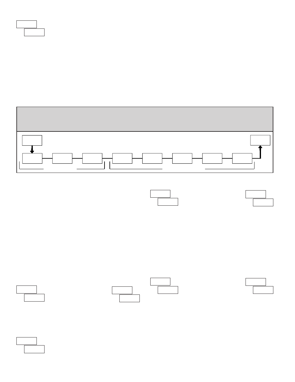
2-FNC
USr-2
USr-1
USr-3
Sc-F1
F1
F2
rSt
Sc-F2
PAR
Pro
FUNCTION KEYS
USER INPUTS
6.2 mOdUle 2 - U
ser
i
npUT
and
f
rOnT
p
anel
f
UnCTiOn
K
ey
p
arameTers
(
)
PARAMETER MENU
The three user inputs are individually programmable to perform specific
meter control functions. While in the Display Mode or Program Mode, the
function is executed the instant the user input transitions to the active state.
The front panel function keys are also individually programmable to perform
specific meter control functions. While in the Display Mode, the primary
function is executed the instant the key is pressed. Holding the function key for
three seconds executes a secondary function. It is possible to program a
secondary function without a primary function.
In most cases, if more than one user input and/or function key is programmed
for the same function, the maintained (level trigger) actions will be performed
while at least one of those user inputs or function keys are activated. The
momentary (edge trigger) actions will be performed every time any of those
user inputs or function keys transition to the active state.
Note:
In the following explanations, not all selections are available for both
user inputs and front panel function keys. Alternating displays are shown
with each selection. Those selections showing both displays are available for
both. If a display is not shown, it is not available for that selection.
will represent all three user inputs.
will represent all five function keys.
NO FUNCTION
No function is performed if activated. This is the factory setting for all user
inputs and function keys. No function can be selected without affecting basic
start-up.
PROGRAMMING MODE LOCK-OUT
Programming Mode is locked-out, as long as activated
(maintained action). A security code can be configured to
allow programming access during lock-out.
ZERO (TARE) DISPLAY
The Zero (Tare) Display provides a way to zero the Input Display value at
various input levels, causing future Display readings to be offset. This function
is useful in weighing applications where the container or material on the scale
should not be included in the next measurement value. When activated
(momentary action),
flashes and the Display is set to zero. At the same
time, the Display value (that was on the display before the Zero Display) is
subtracted from the Display Offset Value and is automatically stored as the new
Display Offset Value (
). If another Zero (tare) Display is performed, the
display will again change to zero and the Display reading will shift accordingly.
RELATIVE/ABSOLUTE DISPLAY
This function will switch the Input Display between Relative and Absolute.
The Relative is a net value that includes the Display Offset Value. The Input
Display will normally show the Relative unless switched by this function.
Regardless of the display selected, all meter functions continue to operate based
on relative values. The Absolute is a gross value (based on Module 1
DSP and
INP entries) without the Display Offset Value. The Absolute display is selected
as long as the user input is activated (maintained action) or at the transition of
the function key (momentary action). When the user input is released, or the
function key is pressed again, the input display switches back to Relative
display.
(absolute) or
(relative) is momentarily displayed at transition
to indicate which display is active.