Eviewing, Ront, Uttons – Red Lion PAXT User Manual
Page 14: Isplay
14
14
Sourcing Logic
Terminals 9-11:
+ VDC through external switching device
Terminal 8:
-VDC through external switching device
In this logic, the user inputs of the meter are
internally pulled down with 22 K resistance.
The input is active when a voltage greater
than 3.6 VDC is applied.
USER
3
USER
2
USER
1
USER COMM
8
9
10 11
Sinking Logic
Terminals 9-11
Terminal 8
In this logic, the user inputs of the
meter are internally pulled up to +5 V
with 22 K resistance. The input is
active when it is pulled low (<0 .9 V).
Connect external
switching device between
appropriate User Input
terminal and User Comm.
+
(30V max.)
SUPPLY
V
USER
3
USER
2
USER
1
USER COMM
9
8
-
11
10
}
PAXH ONLY
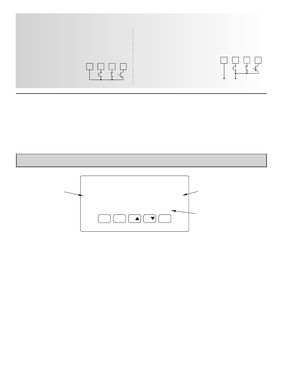
DSP
8.8.8.8.8
X
MA
T
O
T
N
MI
PAR
F1
F2
RST
A
1
S P
S
P
S 2
3
P
P4
S
Display
Readout
Legends*
Optional Custom
Units Overlay
Setpoint Alarm
Annunciators
* Display Readout Legends may be locked out in Factory Settings.
** Factory setting for the F1, F2, and RST keys is NO mode.
RST
F2
F1
PAR
DSP
KEY
Hold with F1
, F2
to scroll value by x1000
Reset (Function key)**
Decrement selected parameter value
Function key 2; hold for 3 seconds for Second Function 2**
Increment selected parameter value
Function key 1; hold for 3 seconds for Second Function 1**
Store selected parameter and index to next parameter
Access parameter list
Quit programming and return to display mode
Index display through max/min/total/input readouts
PROGRAMMING MODE OPERATION
DISPLAY MODE OPERATION
5.0 r
evieWing
THe
f
rOnT
b
UTTOns
and
d
isplay
4.4 SETPOINT (ALARMS) WIRING
4.5 SERIAL COMMUNICATION WIRING
4.6 ANALOG OUTPUT WIRING
See appropriate plug-in card bulletin for details.