Мн о, 3 module 3 - d, Isplay – Red Lion PAXT User Manual
Page 20: Rogram, Arameters
20
20
SETPOINT SELECTIONS
-
Select main or alternate setpoints
-
Reset Setpoint 1 (Alarm 1)
-
Reset Setpoint 2 (Alarm 2)
-
Reset Setpoint 3 (Alarm 3)
-
Reset Setpoint 4 (Alarm 4)
-
Reset Setpoint 3 & 4 (Alarm 3 & 4)
-
Reset Setpoint 2, 3 & 4 (Alarm 2, 3 & 4)
-
Reset Setpoint All (Alarm All)
The following selections are accessible only with the Setpoint plug-in card
installed. Refer to Module 6 for an explanation of their operation.
Setpoint
Card
Only
PRINT REQUEST
The meter issues a block print through the serial port when activated. The
data transmitted during a print request is programmed in Module 7. If the user
input is still active after the transmission is complete (about 100 msec), an
additional transmission occurs. As long as the user input is held active,
continuous transmissions occur.
PROGRAM MODE SECURITY CODE*
By entering any non-zero value, the prompt
will appear when trying
to access the Program Mode. Access will only be allowed after entering a
matching security code or universal code of
. With this lock-out, a user input
would not have to be configured for Program Lock-out. However, this lock-out
is overridden by an inactive user input configured for Program Lock-out.
SP-1 SP-2 SP-3 SP-4 SETPOINT ACCESS*
The setpoint displays can be programmed for
,
or
(See the
following table).
Accessible only with the Setpoint plug-in card installed.
MAXIMUM DISPLAY LOCK-OUT*
MINIMUM DISPLAY LOCK-OUT*
TOTALIZER DISPLAY LOCK-OUT*
These displays can be programmed for
or
. When programmed for
, the display will not be shown when the
DSP key is pressed regardless of
Program Lock-out status. It is suggested to lock-out the display if it is not needed.
The associated function will continue to operate even if its display is locked-out.
3-LOC
LO
HI
tOt
SP-1
SP-2
CodE
PAR
Pro
Min Display
Lock-out
Max Display
Lock-out
Total Display
Lock-out
Setpoint 1
Access
Security
Code
Setpoint 2
Access
SP-3
Setpoint 3
Access
SP-4
Setpoint 4
Access
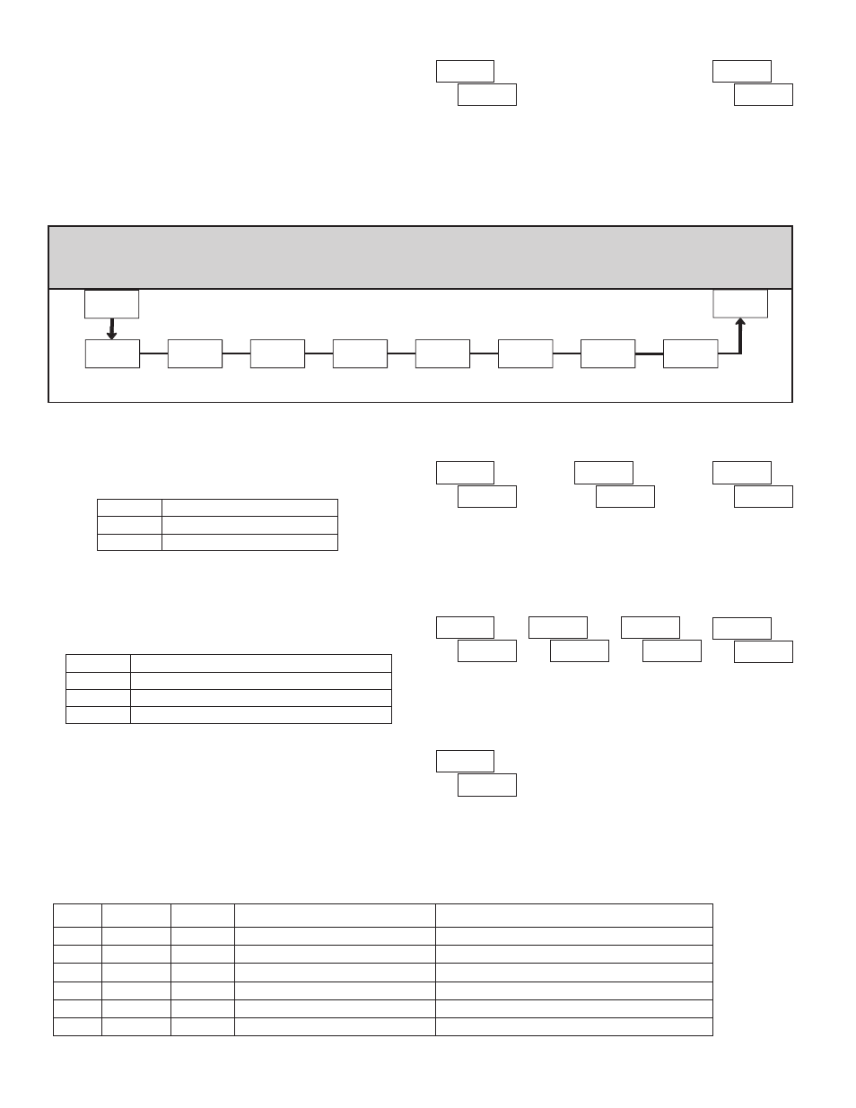
6.3 mOdUle 3 - d
isplay
and
p
rOgram
l
OCK
-
OUT
p
arameTers
(
)
PARAMETER MENU
*
Factory Setting can be used without affecting basic start-up.
to
Module 3 is the programming for Display lock-out and “Full” and “Quick”
Program lock-out.
When in the Display Mode, the available displays can be read consecutively
by repeatedly pressing the
DSP key. An annunciator indicates the display being
shown. These displays can be locked from being visible. It is recommended that
the display be set to
when the corresponding function is not used.
“Full” Programming Mode permits all parameters to be viewed and
modified. This Programming Mode can be locked with a security code and/or
user input. When locked and the
PAR key is pressed, the meter enters a Quick
Programming Mode. In this mode, the setpoint values can still be read and/or
changed per the selections below. The Display Intensity Level ()
parameter also appears whenever Quick Programming Mode is enabled and the
security code is greater than zero.
SELECTION
DESCRIPTION
Visible but not changeable in Quick Programming Mode
Visible and changeable in Quick Programming Mode
Not visible in Quick Programming Mode
Immediate access.
“Full” Programming
Not Active
0
No access
Quick Programming
Active
0
Immediate access.
“Full” Programming
Not Active
>0
After Quick Programming with correct code # at
prompt.
Quick Programming w/Display Intensity
Active
>0
After Quick Programming with correct code # at
prompt.
Quick Programming w/Display Intensity
————
not
>0
Immediate access.
“Full” Programming
————
not
0
“FULL” PROGRAMMING MODE ACCESS
WHEN PAR KEY IS
PRESSED
USER INPUT
STATE
USER INPUT
CONFIGURED
SECURITY
CODE
PROGRAMMING MODE ACCESS
Throughout this document, Programming Mode (without Quick in front) always refers to “Full” Programming (all meter parameters are accessible).
SELECTION DESCRIPTION
Visible in Display Mode
Not visible in Display Mode
м
н
о