Connecting the probe – Vaisala PTU200 User Manual
Page 11
C
HAPTER
3___________________________________________________________ G
ETTING STARTED
V
AISALA
__________________________________________________________________________ 7
At power-up, the display will first show the transmitter type and the
software version. Then it switches to display the reading as defined
with the DFORM command (page 9).
Set the desired sending form according to software settings (described
starting from page 12) and select the sending mode for the transmitter
(see page 11).
Should there be any problems please check the jumper settings in
connector X15 and the settings in dip switch S1 inside the transmitter.
The settings should be as indicated in the figure below.
TXD
RXD
X15
RX/RXD
TX
TXD
ON
OFF
SW1
SW2
SW3
SW4
SW5
SW6
SW7
SW8
S1
F
IGURE
3-2
Basic RS 232C jumper and dip switch S1 settings
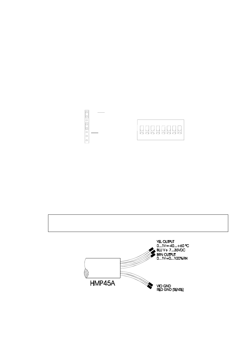
Connecting the probe
As the cable of HMP45A-P is connected via screw terminals the user
can shorten the cable to desired length and reconnect it easily. The
cable wires are connected as shown in
F
IGURE
3-3
.
NOTE
It is not recommend to unsold and then re-sold the wires of HMP45D
and PT100 sensor head.
F
IGURE
3-3
Wire colours of HMP45A-P.