Vaisala PTU200 User Manual
Page 10
U
SER
'
S
G
UIDE
_______________________________________________________________________
6 ____________________________________________________________________ M210195
EN
-A
T
ABLE
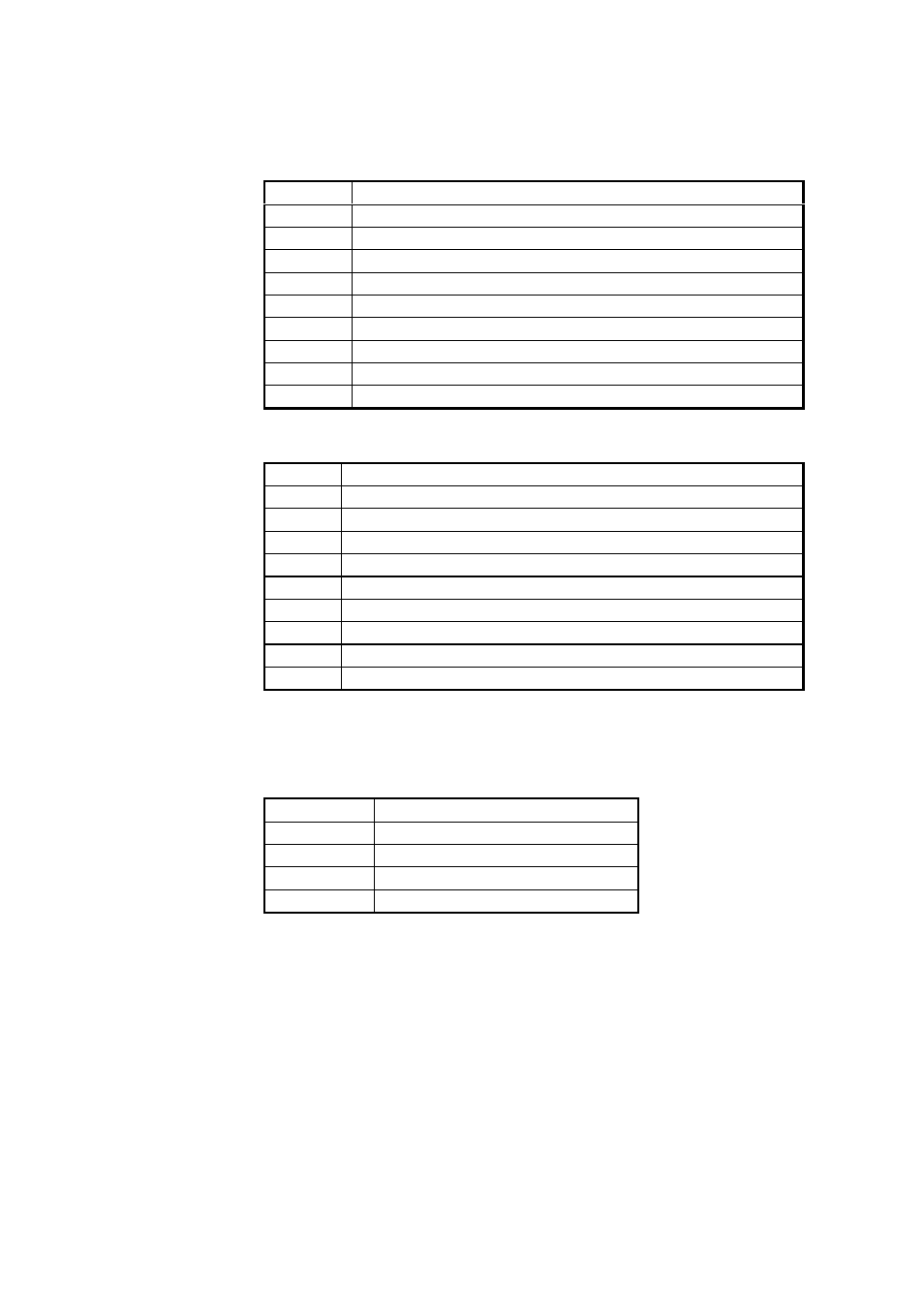
3-1
Pin assignment for RS 232C/TTL serial output
PIN
SIGNAL
1
TX with diode
2
TX/TXD/TXD inverted
3
RX/RXD/RXD inverted
4
external power on/off control
5
ground for the RS 232C
6
7
ground for supply voltage
8
9
supply voltage (10...30 VDC)
T
ABLE
3-2
Pin assignment for optional RS 232C/485/422
PIN
SIGNAL
1
TX with diode
2
TX/TXD/TXD inverted
3
RX/RXD/RXD inverted
4
external power on/off control
5
ground for the RS 232C
6
RS 485/422 LO
7
ground for supply voltage and TTL level serial interface
8
RS 485/422 HI
9
supply voltage (10...30 VDC)
The factory settings of the PTU200 series transmitters are the
following:
T
ABLE
3-3
Serial interface factory settings
Baud rate
9600
Parity
even
Data bits
7
Stop bits
1
Duplex
full duplex
After having made the electrical connections, switch the power on,
and the transmitter responds indicating its type and the software
version.
PTU200 / 1.01
>
The transmitter is now ready to respond to any command available.