Signal and power supply wiring, Figure 20, Screw terminal block on motherboard – Vaisala HMT330 User Manual
Page 39
Chapter 3 ________________________________________________________________ Installation
VAISALA ________________________________________________________________________ 37
Signal and Power Supply Wiring
When connecting the transmitter with 8-pin connector, see section
8-Pin Connector on page 66. When wiring the power supply module, see
section Power Supply Module on page 49.
0506-028
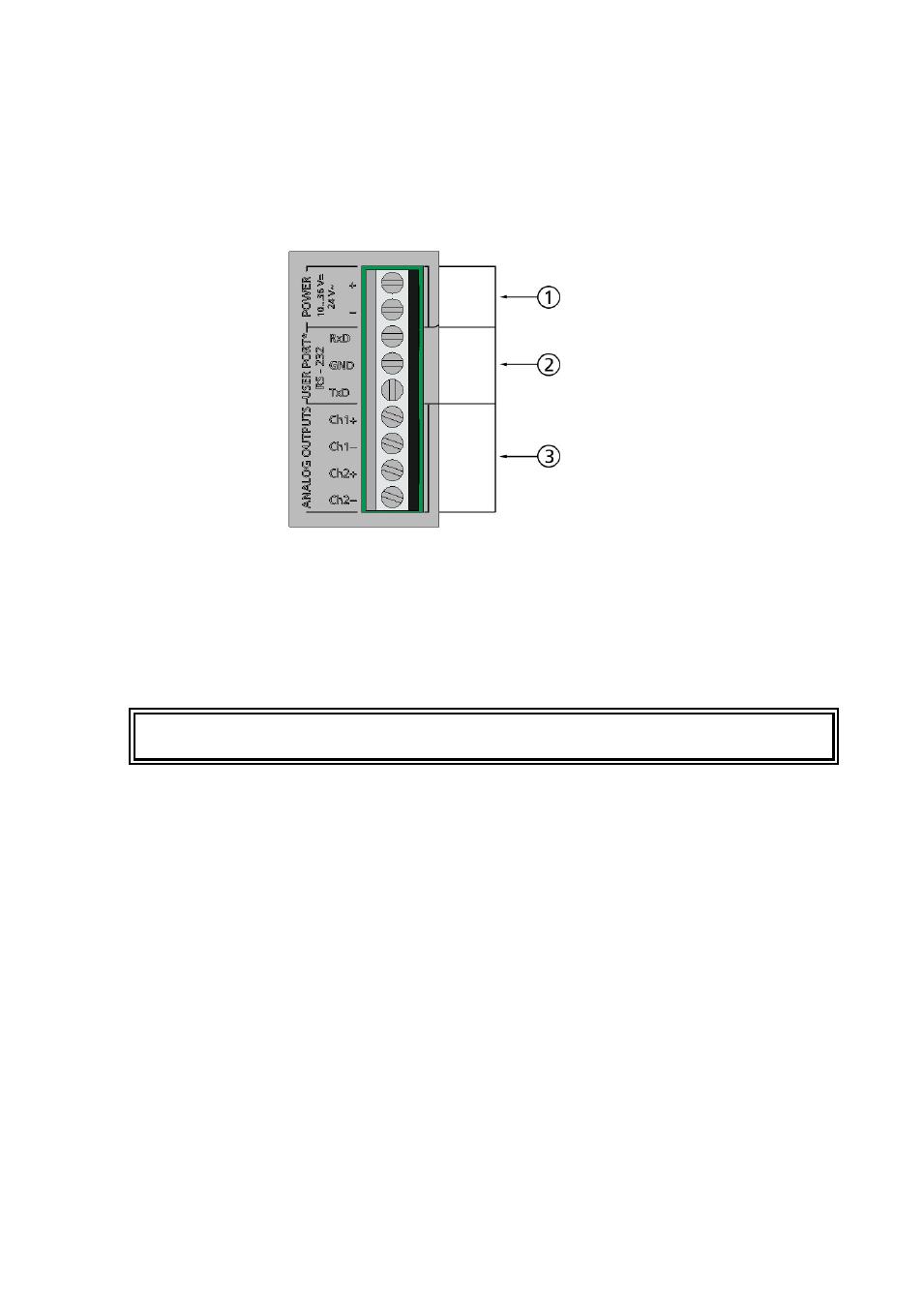
Figure 20
Screw Terminal Block on Motherboard
The following numbers refer to Figure 20 above:
1
=
Power supply terminals 10 ... 35 VDC, 24 VAC
2
=
User port (RS-232 terminals)
3
=
Analog signal terminals
WARNING
Make sure that you connect only de-energized wires.
1.
Unfasten the four cover screws and open the transmitter cover.
2.
Insert the power supply wires and signal wires through the cable
bushing in the bottom of the transmitter; see the grounding
instructions in the previous sections.
3.
Connect the analog output cables to terminals: Ch1+, Ch1-, Ch2+,
Ch2-. Connect the RS-232 user port cables to terminals RxD, GND
and TxD. For more information about the RS-232 connection refer
to section Serial Line Communication on page 79.
4.
When wiring the optional modules, see the corresponding section
for instructions:
- RS-422/485 Interface on page 57
- Relays on page 56
- Third Analog Output on page 54
- WLAN Interface on page 63