Figure 2, Inside the transmitter – Vaisala HMT330 User Manual
Page 24
User's Guide _______________________________________________________________________
22 ___________________________________________________________________ M210566EN-K
0508-010
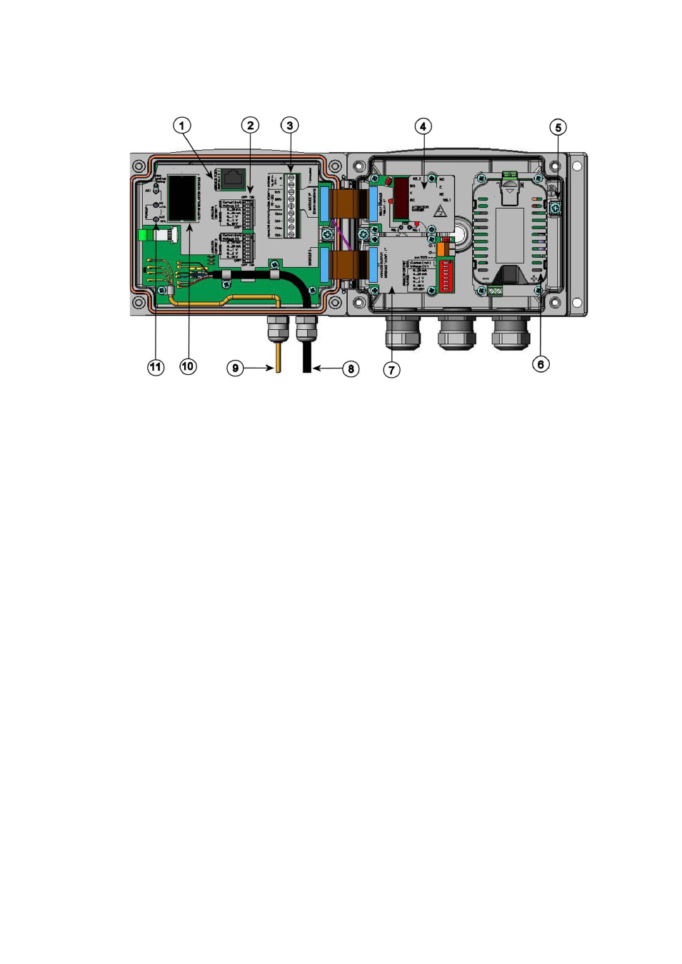
Figure 2
Inside the Transmitter
The following numbers refer to Figure 2 above:
1
=
Service port (RS-232)
2
=
DIP switches for analog output settings
3
=
Power supply and signal wiring screw terminals
4
=
Relay, data logger, RS-422/485, LAN, or WLAN module
(optional)
5
=
Grounding connector
6
=
Power supply module (optional)
7
=
Relay, data logger, or analog output module (optional)
8
=
Humidity probe cable
9
=
Temperature probe cable (optional)
10 =
Galvanic isolation module (optional)
11 =
Adjustment buttons (chemical purge buttons) with indicator
LED
See also other documents in the category Vaisala Humidifiers:
- Calibration of Digital Transmitters with HMI41 (36 pages)
- Calibration of Series HMDW2030 and HMP130 Transmitter with HMI41 (14 pages)
- Calibration of Series HMDW6070 and HMP140 Transmitter with HMI41 (30 pages)
- HM34 (30 pages)
- HM40 (47 pages)
- HM44 (52 pages)
- HM70 (83 pages)
- HMD40 (1 page)
- HMD60 (4 pages)
- HMD70 (18 pages)
- HMDW110 (62 pages)
- HMDW80 (51 pages)
- HMI41 (74 pages)
- HMP41 (72 pages)
- HMK15 (39 pages)
- HMM100 (71 pages)
- HMM105 (23 pages)
- HMM211 (42 pages)
- HMM212 (36 pages)
- HMM213 (52 pages)
- HMP140 (28 pages)
- HMP155 (84 pages)
- HMP228 (115 pages)
- HMP230 (163 pages)
- HMP240 (130 pages)
- HMP260 (118 pages)
- HMP60 (71 pages)
- HMT100 (52 pages)
- HMT120 (87 pages)
- HMT130 (95 pages)
- HMT140 (76 pages)
- HMT310 (88 pages)
- HMT310 (105 pages)
- HMT360 (97 pages)
- HMT360 (63 pages)
- HMT360N (110 pages)
- HMW40 (1 page)
- HMW90 (110 pages)
- SHM40 (68 pages)
- RDP100 (14 pages)