Mate3 screens – Outback Power Systems FLEXmax Extreme Owners Manual User Manual
Page 44
MATE3 Screens
42
900-0150-01-00 Rev A
Table 6
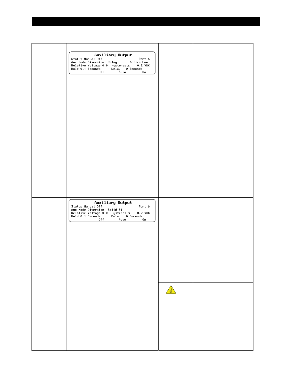
AUX Mode Functions
Mode Name
Function/Purpose
Set Points
Aux Polarity
Diversion:
Relay
Function:
When the battery voltage increases, the AUX
output changes state. The response is relative to
the charger’s present stage of operation. The
voltage must exceed the charger setting
(Absorb, Float, or EQ) by the value of the
Relative voltage. This condition must last for
the Delay time for the AUX to respond.
The AUX returns to its previous state when the
voltage drops below the Relative setting by an
amount equal to the Hysteresis voltage. This
condition must last for the Hold time for the
AUX to respond.
For a wiring diagram illustrating how to connect
this function, see Figure 43 on page 44.
Purpose:
This mode is intended to divert power from the
batteries to prevent overcharging by operating a
diversion load at the appropriate time. The AUX
output operates a mechanical relay which
controls the diversion load. Often used with
wind or hydroelectric sources.
Relative
voltage
Hold time
Delay time
Hysteresis
voltage
Active High: Activates when
battery voltage exceeds the
set point. Usually controls an
auxiliary load to divert power
away from the batteries when
voltage is too high.
Active Low: Activates when
battery voltage drops below
the set point; deactivates
when the voltage exceeds the
set point.
Diversion:
Solid St
Function:
When the battery voltage increases, the AUX
output goes into pulse-width modulation at a
rate of 200 Hz. The response is relative to the
charger’s present stage of operation. The
voltage must exceed the charger setting
(Absorb, Float, or EQ) by the value of the
Relative voltage. This condition must last for
the Delay time for the AUX to respond.
The AUX returns to its previous state when the
voltage drops below the Relative setting by an
amount equal to the Hysteresis voltage. This
condition must last for the Hold time for the
AUX to respond.
For a wiring diagram illustrating how to connect
this function, see Figure 43 on page 44.
Purpose:
This mode is intended to divert power from the
batteries to prevent overcharging by operating a
diversion load at the appropriate PWM level.
The AUX output operates a solid-state relay for
fast and precise control of the diversion load.
Often used with wind or hydroelectric sources.
Relative
voltage
Hold time
Delay time
Hysteresis
voltage
Not Available
IMPORTANT:
Do not use Diversion: Solid St to control a
mechanical relay. The PWM action could
cause irregular relay activity.
Do not use Diversion: Solid St to operate a
diversion load that has anything other than
purely resistive elements. The PWM action
may work poorly with mechanical loads.