Grid-tie mode, Auxiliary output, Mate3 screens – Outback Power Systems FLEXmax Extreme Owners Manual User Manual
Page 41
MATE3 Screens
900-0150-01-00 Rev A
39
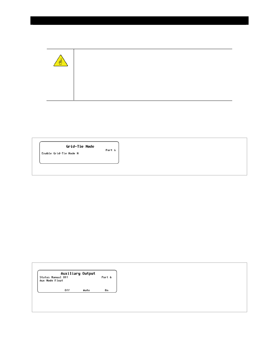
Grid-Tie Mode
IMPORTANT:
This mode requires a grid-interactive inverter model (also known as grid-tie
enabled). Not all inverters are grid-interactive. Also, the inverter’s SELL mode must
be enabled. If the system is connected to an inverter that is not grid-interactive or
not enabled, Grid-Tie mode will not function.
This mode also requires both the inverter and the charge controller to be connected
to the HUB for communication. If an OutBack grid-interactive inverter is present but
both devices are not on the HUB, Grid-Tie mode will not function.
Grid-Tie
mode allows the FLEXmax Extreme to work more effectively with any grid-interactive inverter installed
on the HUB. This setting automatically raises the charge controller’s Float voltage to equal its Absorption
voltage. Since the inverter sells power to maintain its own Float, Absorption, or Sell settings (all of which should
be lower than those of the controller), this mode makes it easier for the inverter to sell power.
See page 65 for more information on this mode.
Figure 41
Grid-Tie Mode
Auxiliary Output
The AUX (Auxiliary) is a secondary control circuit — essentially, a small power supply that provides a 12 Vdc
output current (up to 250 milliamps or 3 watts) to an isolated load. It can be ON with 12 Vdc available at the
output, or OFF with 0 Vdc at the output. It can also be set to AUTO. In this setting, the AUX output turns on or
off according to specific criteria such as high or low voltage. In some cases, such as the PV Trigger, Night Light,
or Diversion: Relay applications, the polarity of the output can be reversed so that the behavior is reversed.
The AUX output can control devices such as cooling fans, vent fans, load diversion, fault alarms, and automatic
generator control. See page 17 for examples of applications.
Only one AUX MODE can be selected or operate at a time (even if other modes have criteria preset).
See Figure 43, page 44, for an auxiliary setup wiring diagram example.
NOTE:
Diversion: Relay
and
Diversion: Solid St
can be used for AC coupling applications.
Figure 42
Auxiliary Output
Set Points:
Two options are available in this menu; N and Y:
~
N (No) disables Grid-Tie Mode;
~
Y (Yes) enables Grid-Tie Mode
Set Points:
Status
– The Auxiliary Output status is controlled by the
Aux Mode
–
Selects one of nine options: Vent Fan, PV Trigger,
Error Output, Night Light, Float, Diversion:Relay,
Diversion:Solid St, Low Battery Disconnect, and Remote.