KROHNE BM 102 Handbook User Manual
Page 71
BM
102
71
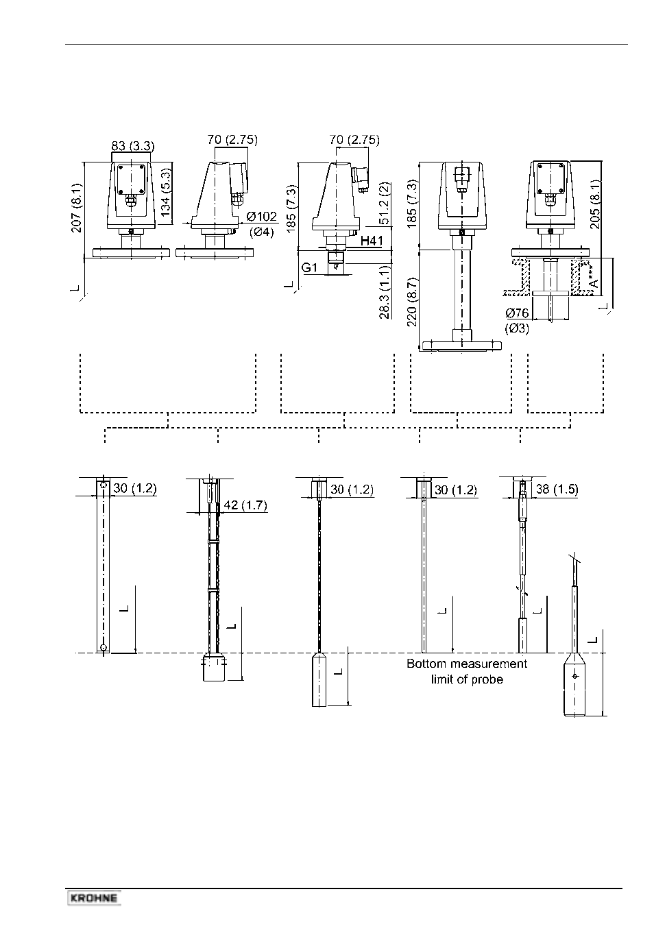
5.3 Gauge
dimensions
This diagram illustrates standard gauge configurations and overall dimensions.
Housing
Standard,
M16 terminal box*
Standard,
DIN
connector** with
threaded
connection
High
temperature
version
With
inactive
length***
Probe
3: Coaxial
Ø 28 (1.1)
4: Twin cable
Ø 4 (0.15)
2: Single cable
Ø 4 (0.15)
1: Single rod
Ø 8 (0.3)
6: Single cable
Ø 8 (0.3)
Standard counterweight
None
Ø45x60
(Ø1¾x2½ )
Ø25x100
(Ø1x4)
None
Ø12x100 (ؽx4)**** or
Ø45x245 (ؽx9¾)*****
Size of threaded hole in base of counterweight for anchoring
None
M8
M8
None
M8
Dimensions in mm (inches)
* with a cable fitting M16X1.5 Ш3.5-Ш8 ** with a cable fitting PG11 Ш8-Ш10 DIN43650-A
*** the inactive length (i.e. a non-active extension at the top of the probe) may be supplied with
the following standard lengths : 100 mm or 4”, 200 mm or 8”, 300 mm or 12”, 400 mm or 16”, 500
mm or 20” and 1 m or 40“ – for single rod and single cable probe versions only.
**** where L
> 10m or > 33ft ***** where L
< 10m or < 33ft L
= ordered probe length
- BATCHFLUX 5500 C Quickstart EN (20 pages)
- IFC 050 Converter Quickstart EN (28 pages)
- IFC 100 Converter Quickstart EN (32 pages)
- IFC 300 Converter Quickstart EN (68 pages)
- OPTIFLUX 1000 Quickstart EN (20 pages)
- OPTIFLUX 2000 Quickstart EN (24 pages)
- OPTIFLUX 4000 Quickstart EN (24 pages)
- OPTIFLUX 4040C Quickstart EN (16 pages)
- OPTIFLUX 5000 Flange Quickstart EN (20 pages)
- OPTIFLUX 5000 Sandwich Quickstart EN (20 pages)
- OPTIFLUX 6000 Quickstart EN (28 pages)
- OPTIFLUX 7300 Quickstart EN (24 pages)
- OPTIPROBE Quickstart EN (16 pages)
- TIDALFLUX 2300 F EN (44 pages)
- TIDALFLUX 2300 F Quickstart EN (24 pages)
- WATERFLUX 3000 EN (40 pages)
- WATERFLUX 3000 Quickstart EN (24 pages)
- WATERFLUX 3070 EN (80 pages)
- WATERFLUX 3070 Quickstart EN (32 pages)
- USB ADAPTER PLUS EMF EN (16 pages)
- IFC 050 Converter Modbus EN (20 pages)
- IFC 100 Converter FOUNDATION FIELDBUS EN (64 pages)
- IFC 100 Converter Modbus EN (20 pages)
- IFC 300 Converter FOUNDATION FIELDBUS EN (60 pages)
- IFC 300 Converter HART 0102 EN (20 pages)
- IFC 300 Converter HART 0201 EN (23 pages)
- IFC 300 Converter Modbus EN (24 pages)
- IFC 300 Converter PROFIBUS PA DP EN (40 pages)
- OPTIFLUX 2000-4000 IECEx EN (16 pages)
- OPTIFLUX 2000-4000-5000-6000-7300-IFC 300 Ex EN (40 pages)
- OPTIFLUX 2000-4000-5000-6000 -IFC 100 Ex EN (24 pages)
- OPTIFLUX 4040 C Ex EN (20 pages)
- OPTIFLUX x300 Ex Zone2 EN (1 page)
- H250 M9 ES EN (36 pages)
- VA 40-VA 45 EN (36 pages)
- H250 M10 ATEX II2G Ex d EN (16 pages)
- H250 M10 ATEX II3D Ex t EN (16 pages)
- H250 M40 ATEX II2D Ex t-II2G Ex d EN (20 pages)
- H250 M40 ATEX II2G Ex i EN (20 pages)
- H250 M40 ATEX II3G Ex nA EN (20 pages)
- H250 M40 Ex II2G Reed EN (2 pages)
- H250 M9 ATEX II2G Ex i EN (16 pages)
- H250 M9S ATEX II3D Ex t-II3G Ex nA EN (20 pages)
- M8E Converter HART 0101 EN (13 pages)
- DK 32-DK 34 ATEX II2G Ex i EN (16 pages)