KROHNE BM 102 Handbook User Manual
Page 16
16
BM 102
1.3.5 Specific
installation
instructions: gauge - solid applications
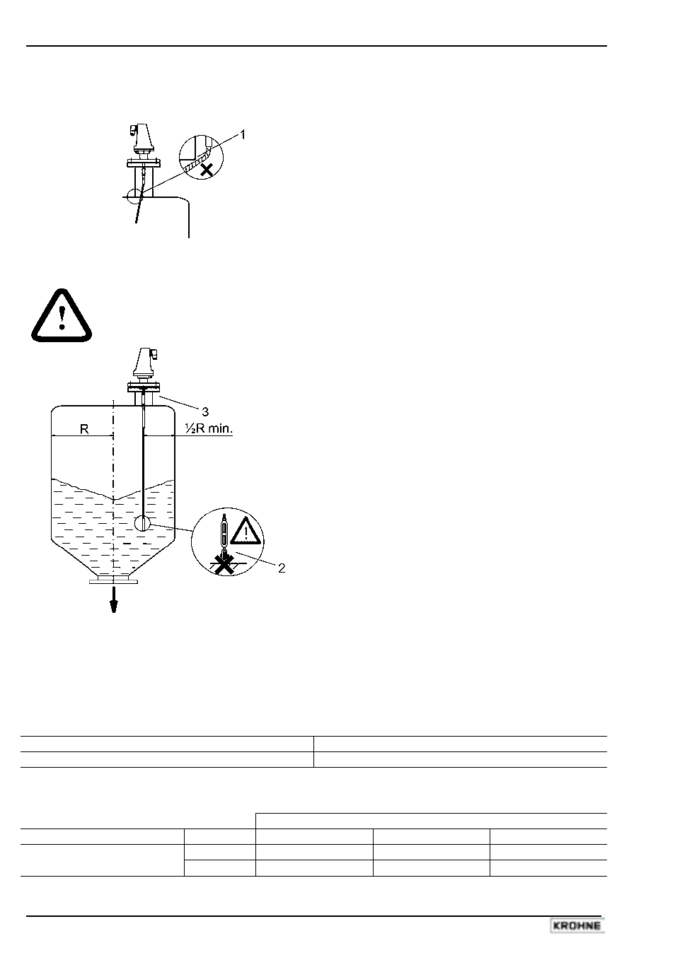
False readings:
1
Do not let probe touch the side of the nozzle
Conical silo nozzles, false readings and traction on the cable probes
Caution
High traction forces :
2
We recommend that the probe should not be
anchored to avoid excessive traction loads on
the cable.
Bending and traction:
3
Position the connection on the roof at ½
radius of the tank and with minimum nozzle
height. This will avoid damage due to bending
and traction during emptying.
Traction forces during emptying cycles for powder applications
Traction load is dependent upon the height and shape of the tank, product particle size & density,
and the rate at which the tank is emptied. The table below gives the load up to which cable probes
will hold.
Cable maximum design load, traction
Probe Maximum
Load
Single cable Ø8 mm or Ø0.3”
3.5 T or 7700 lb
Traction on cable according to product (approximate value in metric tons)
Probe Length / m (ft)
Probe used
Material
10 (33) 20
(65.5) 24
(79)
Cement
1.0 T or 2200 lb
2.0 T or 4410 lb
2.4 T or 5290 lb
Single cable Ø8mm or
Ø0.3”
Flyash
0.5 T or 1100 lb
1.0 T or 2200 lb
1.2 T or 2650 lb