9 power supply – KROHNE BM 70 A_P EN User Manual
Page 63
Installation and operating instructions BM 70 A/P
Page: 63
11/00
9 Power supply
9.1 Options, technical data
A choice is offered of 2 supply power versions:
Version
Voltage U
Tolerance
= voltage
range
Frequency
Power
(typical) *
max. ripple /
harmonics
24V DCAC
24 V DC
-25%
+30%
18-31.2 V
-
7.5 - 10 W
within limits of
tolerance
24 V AC
-25%
+10%
18-26.4 V
45-66 Hz
10 VA
10%
115/230V
AC
115 V AC
-25%
+10%
85-127 V
45-66 Hz
12 VA
10%
230 V AC
-25%
+10%
170-254 V
45-66 Hz
12 VA
10%
* Hazardous-duty limit: 20W / 40 VA
9.2 Fuses
Device-internal fuses for power:
24 V DCAC*
T 1.25 A
115 V AC**
T 315 mA
230 V AC**
T 160 mA
*: Terminals 1 and 2 are both fuse-protected.
**: Only connection L (for TN system) is fuse-protected;
optionally also both connections N and L (for IT system), see Sect. 9.3.
Location of fuses on the "line" board and replacement of fuses: see Sect. 9.3.
In accordance with operative regulations, it may be necessary to provide additional fuse protection
when installing the system.
Recommended line fuse protection:
24 V DCAC
min. T 2 A
115 V AC
min. T 0.5 A
230 V AC
min. T 0.25 A
9.3 Changeover of operating voltage and replacement of fuses
Always switch off power source before commencing work!
Hazardous-duty systems:
Before opening the "flameproof enclosure" (large cover on the signal converter) in the hazardous
area, make absolutely certain that there is no explosion hazard. Allow the prescribed waiting time of
10 minutes to elapse first!
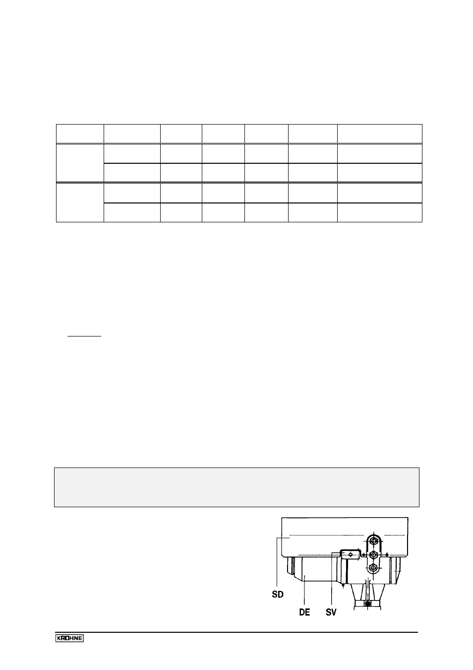
1. Unscrew sunshade SD, if fitted.
2. Detach safety lock SV using Allen key (size 4 mm).
3. Remove cover DE from the electronic compartment
(flameproof enclosure) with the supplied special wrench.