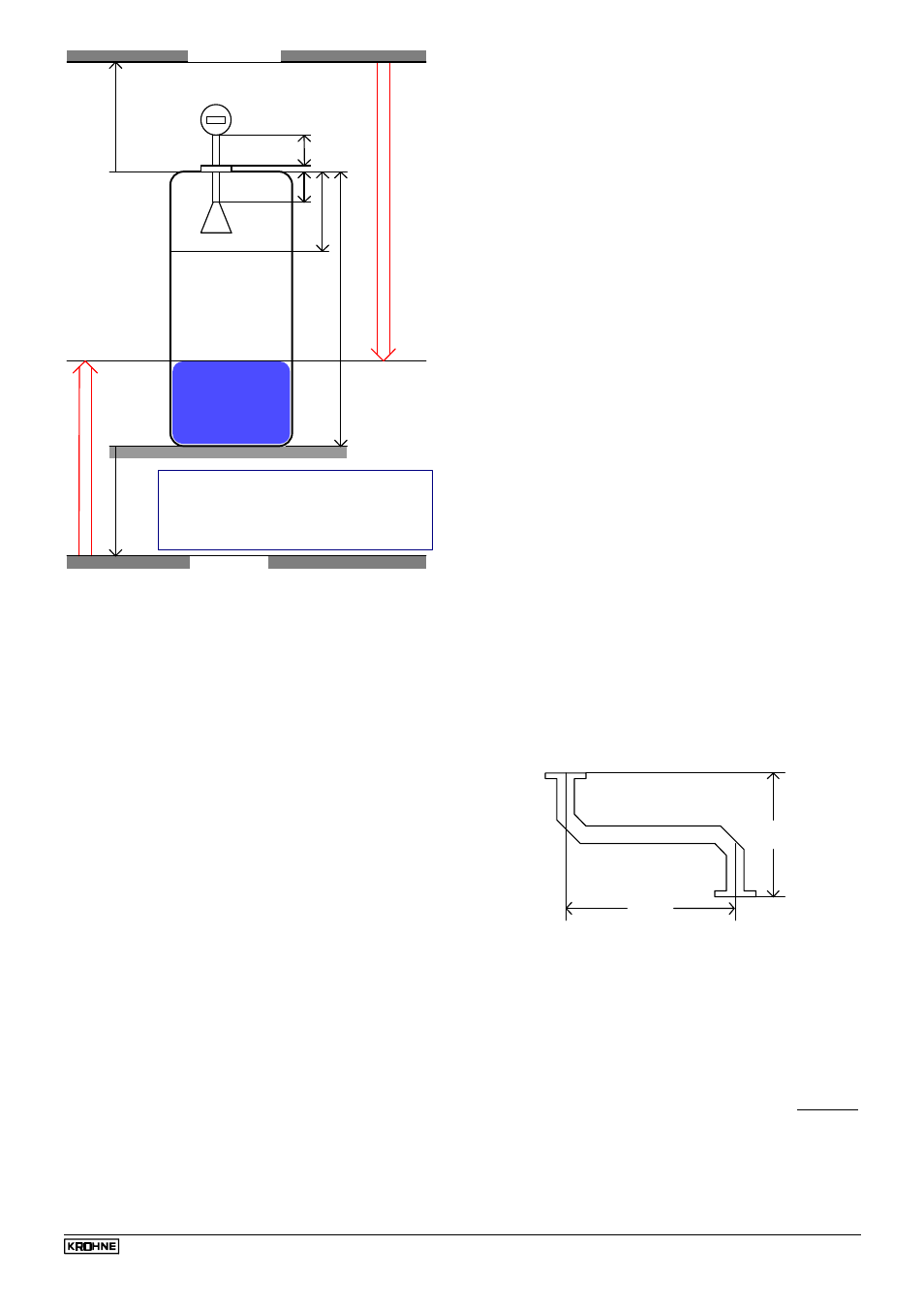
2 vessel (tank) height fct. 3.1.1 tankheight, 4 distance piece – KROHNE BM 70 A_P EN User Manual
Page 45
Installation and operating instructions BM 70 A/P
Page: 45
11/00
H
AV
BD
O-Ref (+)
O-TB (+)
DS
O-Ref
O-TB
H
AV
BD
- Antenna extension
Fct. 3.1.1 [0.00 m ... max. tank height]
Fct. 3.1.4 [0.00 m ... Tank height]
Fct. 3.1.2 [0.10 m ... Tank height]
Fct. 3.1.7 [ -10.00 ... + 10.00 m]
Fct. 3.1.8 [ -100.00 ... + 100.00 m]
DS
Fct. 3.1.5 [0 ... 2000 mm]
Bottom edge of flange
Product surface
datum plane for distance
Level
tank bottom
distance
- tank height
- block distance
- distance piece
- reference offset
- tank bottom offset
datum plane for level
8.6.2 Vessel (tank) height
Fct. 3.1.1 TANKHEIGHT
•
Definition of the tank height for the BM 70 A/P:
Distance between the top edge of the tank fitting and
the lower reference point.
•
The lower reference point is that "point" in the vessel
on which the microwaves emitted by the BM 70 A/P
impinge and from which they are reflected. This can be
the tank bottom (sy mmetrical tank with flat bottom) or
the non-horizontal part of the bottom (e.g. tank with
dished bottom) or an additionally fitted plate. The
BM 70 A/P cannot measure below the lower reference
point (usually a "sump" is left in the tank, see diagram
in Sect. 8.5).
•
Selection of unit, see Sect. 8.6.1.
•
Setting ranges for the tank height BM 70 A (standard):
•
00.50 - 40.00 m
•
0050 - 4000 cm
•
00500 - 40000 mm
•
0019.7 - 1574.74 inch
•
001.64 - 131.22 ft
For BM 70 P: max. 35m / 1377.9 inch / 114.8 ft
•
Depending on the version, it is also possible to set an
upper limit for the tank height (e.g. Wave-Stick: 20 m).
The maximum value can be increased by KROHNE
Service to up to 100 m. (For BM 70 A only)
•
The tank height set at this point is simultaneously the
upper limit of the setting ranges for the following
functions:
- Block distance, Fct. 3.1.2
- Antenna extension, Fct. 3.1.4
- Hysteresis, switching output, Fct. 3.6.4
•
If the tank height is changed to a value greater than 30
m, a new empty spectrum must subsequently be
recorded, see Sect. 8.6.12. (not applicable to BM 70P).
8.6.3 Block distance, antenna type and antenna
extension
Fct. 3.1.2 BLOCKDIST
•
Caked deposits or contamination of the antenna, for
example, can cause faulty measurements directly
below the antenna. The function "block distance" is
used to specify a zone below the flange in which
measurements are not to be carried out.
•
Signals within the block distance are suppressed; a
rise in the level above this limit will result in a
measurement corresponding to a distance = block
distance, when Fct. 3.5.6 BD-DETECT = ON.
•
Unit and setting range: same as Fct. 3.1.1
TANKHEIGHT.
•
Recommended minimum value (see also Sect. 3.3):
- for "Wave-Stick": 200 mm
- for stilling wells and "Wave-Stick SW":
antenna length + 300 mm
- all other versions in storage tanks:
antenna extension + antenna length + 100 mm
- all other versions in process tanks:
antenna extension + antenna length + 200 mm
Fct. 3.1.3 ANTENNA
•
The antenna type is factory-set here.
•
STANDARD (all versions incl. "Wave-Stick SW" but
excl. "Wave-Stick")
•
WAVESTICK (not for "Wave-Stick SW")
•
BM 70 P: only STANDARD setting possible.
Fct. 3.1.4 ANT.EXTENS.
The length of the supplied antenna extension is factory-set
here.
•
Unit and setting range: same as Fct. 3.1.1
TANKHEIGHT.
This setting may only be changed when a longer or shorter
antenna extension is installed. Otherwise faulty measure-
ments may result because the BM 70 A/P allows for this
length when measuring. After changing any antenna
extension, record a new empty spectrum, see Sect. 8.6.12.
When a curved antenna extension is used, only the
vertical component (vertical offset) should be entered
here.
Example (S-shaped extension): Fct. 3.1.4 = 323 mm.
323 mm
300 mm
(Fct. 3.1.4)
(Fct. 3.1.5)
8.6.4 Distance piece
Fct. 3.1.5 DIST.PIECE
The length of any supplied distance piece above the
mounting flange is factory-set here.
•
Setting range: 0 ... 2000 mm
•
Default value: 0 mm
The value of 120 mm should be entered for the high-
temperature version of the flange system.
When a curved antenna extension is used, the horizontal
component of this extension should additionally be entered
(= geometric length of the pipe minus the vertical offset).
Example (see drawing above): Fct. 3.1.5 = 300 mm.