7 functional checks – KROHNE BM 70 A_P EN User Manual
Page 55
Installation and operating instructions BM 70 A/P
Page: 55
11/00
8.7 Functional checks
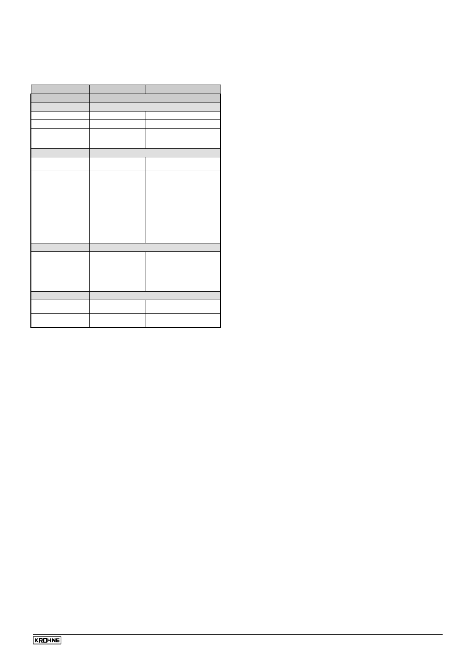
8.7.1 main menu 2.0 Test functions
Function (Fct.)
Input range
Description
2.0 TEST
2.1.0 HARDWARE
2.1.1 MASTER
Special function
Test of master hardware.
2.1.2 DISPLAY
Special function
Test of display hardware.
2.1.3 STATUS
Select
Module DIS
Module MW
Display of ID Number and
status bytes.
2.2.0 CUR.OUTP.I
2.2.1 VALUE I
Display of value
Display of actual value of
the current output.
2.2.2 TEST I
Options
2 mA
4 mA
6 mA
8 mA
10 mA
12 mA
14 mA
16 mA
18 mA
20 mA
22 mA
Output of selected value to
the current output.
NOTE !!! With safety inquiry
because current output is
accessed direct !!!
(Exi = min. 3.6 mA)
2.3.0 SW.OUTP.
2.3.1 TEST S
Options
OPEN
CLOSED
Switches the switching
contact on/off.
NOTE !!! With safety inquiry
because current output is
accessed direct !!!
2.4.0 FIRMWARE
2.4.1 MASTER
Display
Display of master firmware
version.
2.4.2 DISPLAY
Display
Display of master firmware
version.
8.7.2 Hardware test
Testing of the BM 70 A/P hardware can be initiated as
required with these functions when the device is operating.
When an error is established, a message appears in the
display (see Sect. 8.8). This hardware test is carried out
automatically every time the BM 70 A/P is started up.
Fct. 2.1.1 MASTER
•
Select Function 2.1.1, as described in Sect. 8.2 and
8.3.
•
"TEST" is shown in the display during the automatic
test, followed by "READY" on completion of the test.
•
During the test the current output holds the last
measured value; digital Communication is not possible
during that time.
Fct. 2.1.2. DISPLAY
•
Select Funtion 2.1.2, as described in Sect. 8.2 and 8.3.
•
Press the
→
key; all segments in the display are
switched on.
•
Press
↑
key; all segments are switched off.
•
This procedure (switching on/off) can be repeated any
number of times with the
↑
key.
•
Press the
↵
key to terminate the test.
Fct. 2.1.3 STATUS
After selecting "Module DIS" or "Module MW" after
pressing the
↵
key in each case an Identity Number and
an 8-digit binary number are displayed. If an undefined
error occurs, please inform KROHNE Service of these
values. Terminate the test by pressing the
↵
key twice.
8.7.3 Test of current output
Fct. 2.2.1 VALUE I
•
Select Function 2.2.1, as described in Sect. 8.2 and
8.3.
•
Press
→
key to display the actual value of the current
output (terminals 31 and 32) in "mA".
•
Terminate test by pressing the
↵
key.
Fct. 2.2.2 TEST I
•
A millia mmeter should be connected to terminals 31
and 32 for this test, see Sect. 7.8
•
Select Function 2.2.2, as described in Sect. 8.2 and
8.3.
•
Press
→
key.
•
Safety inquiry: SURE NO
SURE YES
}
Select with
↑
key
After SURE YES, press the
↵
key for the 1st value in the
following list to be present at the current output.
•
Select current values with the
↑
key:
2 mA
14 mA
4 mA
16 mA
6 mA
18 mA
8 mA
20 mA
10 mA
22 mA
12 mA
•
The connected millia mmeter indicates the selected
current value.
•
For instruments with Ex-i current output: in the 2 mA
setting the minimum current of 3.6 mA is output.
•
Terminate the test by pressing the
↵
key, and the
actual measured value is again present at the current
output.
8.7.4 Test of switching output
Fct. 2.3.1 TEST S
•
In this test, the switching contact (terminals 41 and 42)
can be closed or opened.
•
Select Function 2.3.1 as described in Sect. 8.2 and
8.3.
•
Press the
→
key.
•
Safety inquiry: SURE NO
SURE YES
}
Select with
↑
key
•
After SURE YES, press
↵
key.
•
Displayed: OPEN = switching contact is open.
•
Press the
↑
key.
•
Displayed: CLOSED = switching contact is closed.
•
Terminate the test by pressing the
↵
key, and the
switching output will resume its normal operating
condition.
8.7.5 Display of firmware version
Fct. 2.4.1 MASTER
This function shows the current main firmware version
(e.g. V.3.00) in the configuration menu.
Fct. 2.4.2 DISPLAY
This function shows the current firmware version of the
display part.