5 selection of antenna type and size – KROHNE BM 70 A_P EN User Manual
Page 31
Installation and operating instructions BM 70 A/P
Page: 31
11/00
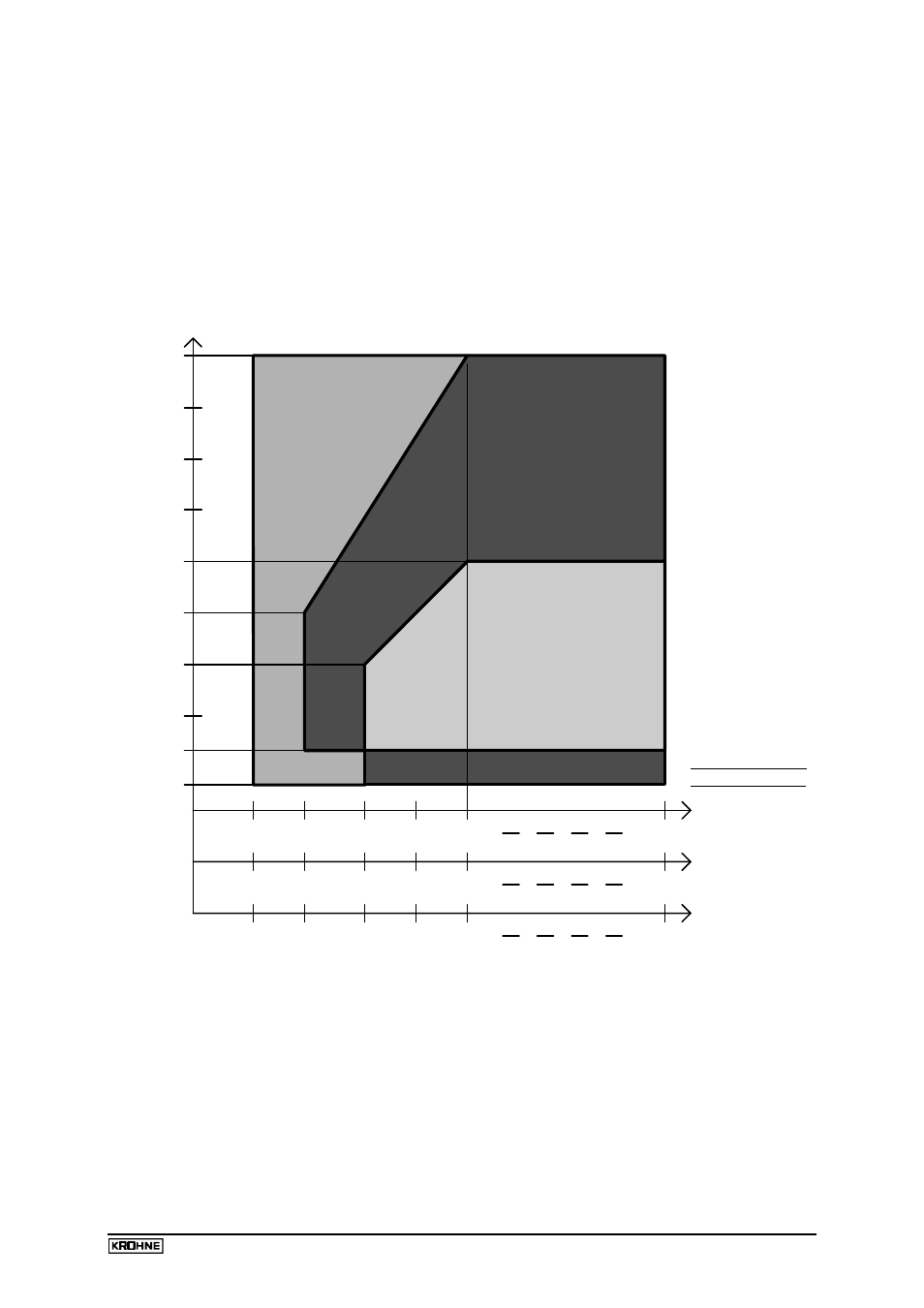
7.5 Selection of antenna type and size
This BM 70 A recommendation for the optimum application range is based on application
experience and designed to minimize potential problems. If the recommended antenna is
unacceptable, any other configuration may also be tested.
Type 1 and 2 antennas should only be used with stilling wells.
For BM 70 P always antenna type 4 or a stilling well > 100 mm / 4" is recommended.
40m
15m
10m
1.5m
0.5m
∞
1.5
2
8
3
∞
2
15
3
5
∞
2
30
4
8
15
10
5
25m
20m
5m
30m
ε
r
ε
r
ε
r
35m
tank height/
range
Dielectric constant
or foam
with vortex
process tank
agitator tank
of the medium for:
smooth surface
antenna type 4
antenna type 3
Wave-Stick
stillwell
stillwell
Wave-Stick
stillwell
stillwell
antenna type 4
stillwell
130ft
45ft
30ft
5ft
1.6ft
85ft
65ft
15ft
100ft
115ft
storage tank with
How to use the diagram:
•
Determine the following application parameters:
a) Tank height or maximum measuring range/distance (e.g. H=15m)
b) Tank type (one of the three types shown, e.g. process tank)
c) Relative permittivity of the product (e.g.
ε
r=5)
•
Find the relative permittivity on the relevant horizontal axis (e.g. 5 on the middle axis)
•
Draw a line up to the required tank height = vertical axis (e.g. 15 m)
•
The end of the line defines the application range. The text contained in that area indicates
the suitable antenna types (in the example: stilling well or Type 4).