5 stilling well – KROHNE BM 70 A_P EN User Manual
Page 46
Installation and operating instructions BM 70 A/P
Page: 46
11/00
8.6.5 Stilling well
Fct. 3.1.6 STILLWELL
If the device is operated with a stilling well, the option
Stilling well = YES and the inside diameter of the pipe
should be entered here in mm.
•
NO
: operation without stilling well
•
YES : operation with stilling well
If YES has been selected, proceed with
↵
and enter the
inside diameter:
•
Setting range: 25 ... 200 mm
•
Default value: 100 mm
If the diameter of the stilling well is greater than 200 mm,
enter the maximum value = 200 mm.
8.6.6 Reference and tank bottom offsets
Fct 3.1.7 REF. OFFSET
An arbitrary reference offset is added to the measured
distance (positive when the reference point is above the
flange; negative when the reference point is below the
flange): see Example 1 below. The offset is effective for all
distance values (local display, current output, switching
output, digital information).
•
Setting range: -10 m ... +10 m (32.8 ft)
•
Default value: 0
Fct 3.1.8 TB.OFFSET
An arbitrary tank bottom offset is added to the measured
level (positive, when the reference point is below the set
tank height; negative, when the reference point is above
the tank bottom): see Examples 2 and 3. The offset acts
on all level values (local display, current output, switching
output, conversion table, digital information).
•
Setting range: -99.99 m ... +99.99 m (328 ft)
•
Default value: 0
Examples of setting the reference offset and tank
bottom offset:
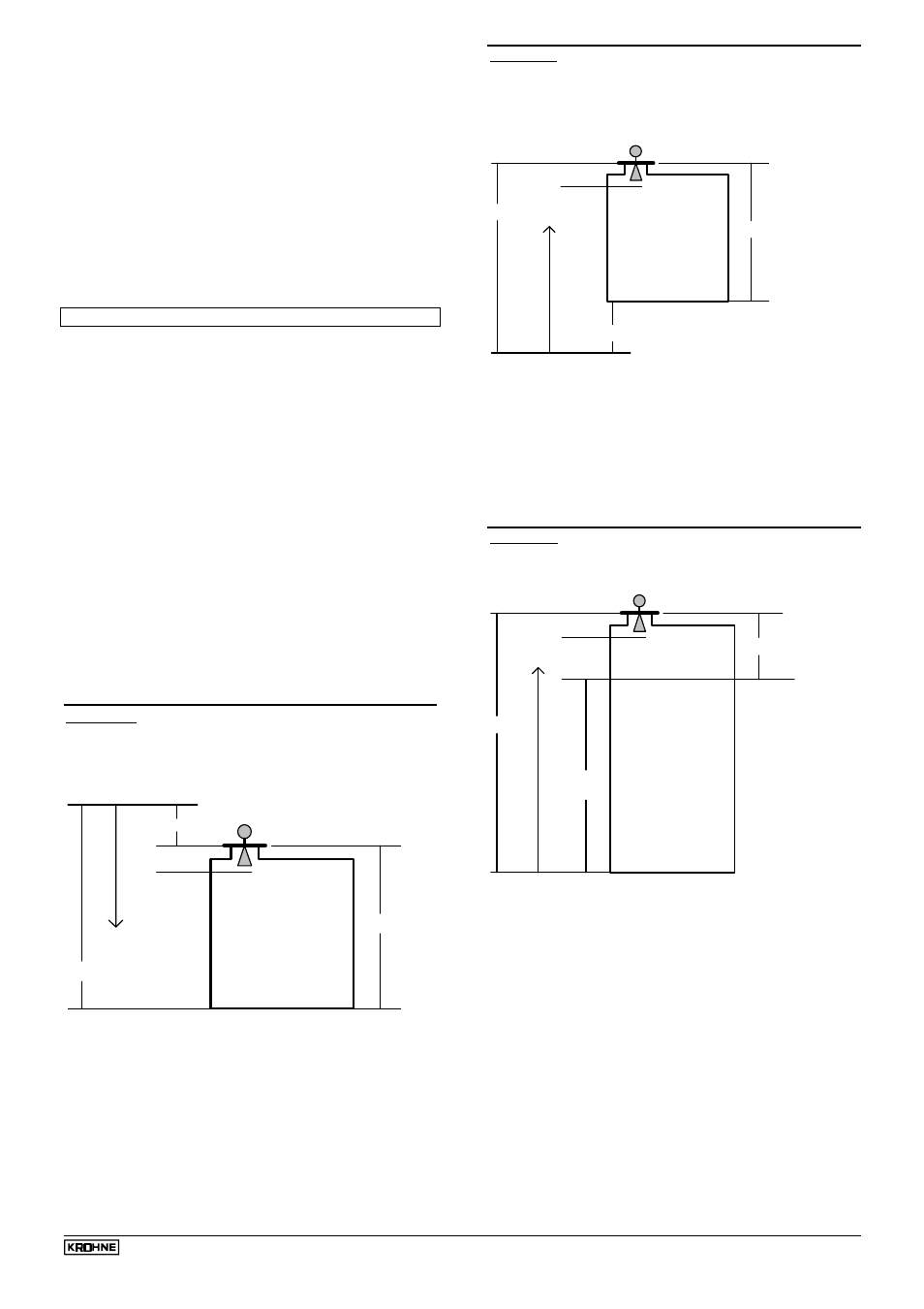
Example 1: Reference point for distance measurement
(ullage) differs from flange position (in the example, 1 m
above the flange). Let the tank height be H = 6 m.
H = 6m
BM 70 Reference point
Reference plane
for distance measuring
RO = 1m
"Ullage"
7m
Block-
distance
Input the following parameters:
Tank height = 6 m
Reference offset = + 1 m
Tank bottom offset = 0
The possible measuring range is:
Distance = (1 m + block distance) to 7 m.
Example 2: Reference point for level measurement differs
from the progra mmed tank bottom position (in the
example, 2 m below the tank bottom). Let the tank height
be H = 6 m.
H = 6m
BM 70 Reference point
Reference plane
for level measurement
8m
Tank bottom
TBO = 2m
Block-
distance
Level
Input the following parameters:
Tank height = 6 m
Tank bottom offset = + 2 m
Reference offset = 0
The possible measuring range is:
Level = 2 m to (8 m - block distance).
Example 3: Only a specific part of the level in a very tall
tank is to be measured (in the example, levels 50m ...
60m).
10m
60m
tank bottom
TBO =
50m
programmed
Block
distance
BM 70 Reference point
Level
Reference plane
for level measurement
Input the following parameters:
Tank height = 10 m
Tank bottom offset = + 50 m
Reference offset = 0
The possible measuring range is:
Level = 50 m to (60 m - block distance).